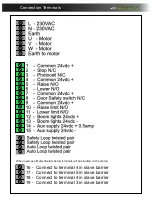
1. Inputs
Input
Polarity
Connected to
Operation when active
I0
Normally closed
Kerb lowered
Stops the barrier from raising when kerb interlock ON
I1
Normally Closed
Stop circuit
Barrier stops if door open
I2
Normally Open
Raise signal
Raises Barrier
I3
Normally Open
Lower signal
Lowers barrier
I4
Normally Open
Raise limit switch
Arm has reached its fully open position
I5
Normally Open
lower limit switch
Arm has reached its fully closed position
I6
Normally Open
Safety loop Detector/Photocell
Barrier stops and returns the the raise position until clear.
I7
Normally Open
Auto Loop
Raises the barrier from the auto loop
2. Outputs
Output:
Polarity:
Connected to:
Operation when active:
Q0
Normally Open
Motor controller slow down
Active to slow barrier down
Q1
Normally Open
Motor controller open direction
Active to Raise barrier
Q2
Normally Open
Motor controller close direction
Active to lower barrier
Q3
Normally Open
Boom Lights
Active to operate boom lights
Q4
Normally Open
Traffic light relay
Active when green light in
Q5
Normally Open
Maglock or siren
Active to operate maglock or siren (depending on parameters)
Q6
Normally Open
Slave raise or Barrier raised
Active to raise the slave barrier or give barrier raised output
Q7
Normally Closed
Slave Safety/close or barrier lowered
Active to lower the slave safety or give barrier lowered output
D
3250
Electrical Troubleshooting guide.
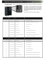
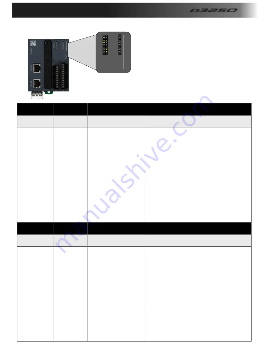
The table (bottom) relates to the diagram directly below to help you trouble shoot electrical
component errors
PWR
BAT
RUN
EROR
SD
0
1
2
3
4
5
6
7
0
1
2
3
4
5
6
7
IN
OUT
M
2
2
1
T
M
2
2
1
M
1
6
R
The image on the left shows the input and output
LED indicators, use these with the chart below
To identify any faults with the barrier. The example
On the left shows that the barrier is lowered, the
Photocells/loop are healthy and the stop circuit is
Also healthy.
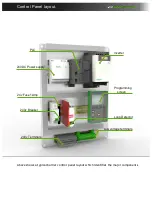
Note, the PLC is located in the barrier cabinet.

