


WCT1012VLF/WCT1013VLH Consumer MP-A11 (WCT-15W1CFFPD) V1.0 Wireless Charging Applicati
on User’s
Guide, Rev. 1, 05/2019
NXP Semiconductors
9
4.4. Rail voltage generated by analog buck chip
The Qi specification for the MP-A11 topology requires the DC voltage control to control the power
transferred to the receiver. The buck converter is selected to get the regulated DC voltage ranging from
3 V DC to 18 V DC for the full-bridge inverter power supply. The buck is controlled by the individual
analog buck converter and the WCT chip only controls the output voltage feedback.
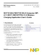
For the analog buck module, MP2229 (or a similar IC like SY8286) is selected to generate the rail
voltage. The WCT chip generates one analog signal from the PWM and controls the rail voltage using
this signal. This analog signal adjusts the analog buck converter feedback, and the system can get the
rail voltage as the system expects.
Figure 7. Analog buck-boost main circuits
4.5. Full-bridge and resonant circuits
The full-bridge power stage consists of integrated power stage unit (U7 and U8). The MOSFETs and
their driver are integrated inside the power stage unit. The full-bridge power stage converts the variable
DC voltage VRAIL to the square-wave 50 % duty-cycle voltage with a default frequency of 127.772
kHz. The range of the frequency used (from 120 kHz to 130 kHz) is defined in the Qi specification for
the MP-A11 topology.
The resonant circuits consist of C81, C82, C83, C84, C85, and coils, all of which are fixed values
defined in the Qi specification for the MP-A11 topology. The snubber RC pairs connected in parallel to
the integrated power stages are used to lower the high frequency of the EMI products. The Vrail
discharge circuit (Q4 and R58) is switched ON while the system is terminated.