


WCT1012VLF/WCT1013VLH Consumer MP-A11 (WCT-
15W1CFFPD) V1.0 Wireless Charging Application User’s
Guide, Rev. 1, 05/2019
NXP Semiconductors
3
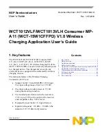
2.2. Board description
The WCT board is powered through the on-board power connector.
The connectors on the upper-middle part of the board provides the JTAG connection for programming
and debugging and 1xUART for the FreeMASTER tool connection for the debug option and console
connection. The I
2
C connector is placed on the upper left-hand side of the board.
Coil
I2C
UART
JTAG
DSC
USB PD
Buck
FB
Invertor
Power
Figure 2. Device overview
2.3. Powering the board on
To power the board on, perform these steps:
1.
Plug the USB PD or QC adaptor.
2.
Connect the board with the USB PD or QC adaptor by an USB type-C cable.