


WCT1012VLF/WCT1013VLH Consumer MP-A11 (WCT-
15W1CFFPD) V1.0 Wireless Charging Application User’s
Guide, Rev. 1, 05/2019
NXP Semiconductors
11
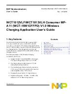
Figure 9. Power loss illustrated
When the FO is implemented in the power transfer, the power loss increases accordingly, and the FO
can be detected based on the power loss method.
The power loss FOD method is divided into two types: FOD for the baseline power profile (TX and RX
can transfer no more than 5 W of power) and extensions power profile (TX and RX can transfer power
above 5 W).
Power-loss FOD baseline
The equation for the power-loss FOD baseline is
𝑃
𝐿𝑂𝑆𝑆
= 𝑃
𝑃𝑇
− 𝑃
𝑃𝑅
.
The Transmitted Power
𝑃
𝑃𝑇
represents the amount of power that leaves the TX due to the magnetic field
of the TX, and
𝑃
𝑃𝑇
= 𝑃
𝑖𝑛
− 𝑃
𝑃𝑇𝑙𝑜𝑠𝑠
, where
𝑃
𝑖𝑛
represents the input power of the TX and
𝑃
𝑃𝑇𝑙𝑜𝑠𝑠
is the
power dissipated inside the TX.
𝑃
𝑖𝑛
can be measured by sampling the input voltage and input current,
and
𝑃
𝑃𝑇𝑙𝑜𝑠𝑠
can be estimated using the coil current.
The Received Power
𝑃
𝑃𝑅
represents the amount of power that is dissipated within the RX due to the
magnetic field of the TX, and
𝑃
𝑃𝑅
= 𝑃
𝑂𝑢𝑡
+ 𝑃
𝑃𝑅𝑙𝑜𝑠𝑠
. The power
𝑃
𝑂𝑢𝑡
is provided at the RX output and
𝑃
𝑃𝑅𝑙𝑜𝑠𝑠
is the power lost inside the RX.
When the NXP MP-A11 transmitter charges the baseline profile RX, the power-loss baseline is applied.
The TX continuously monitors
𝑃
𝐿𝑂𝑆𝑆
, and if it exceeds the threshold several times, the TX terminates
the power transfer.