WCT1012VLF/WCT1013VLH Consumer MP-A11 (WCT-
15W1CFFPD) V1.0 Wireless Charging Application User’s
Guide, Rev. 1, 05/2019
38
NXP Semiconductors
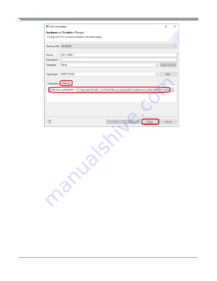
Figure 45. Memory configuration
10.
Select “USB TAP” for the “Connection type”, and then click “Finish”.
Страница 1: ...t voltage ranges from 5 to 19 V DC The input voltage can drop down to 5 V DC during the start stop function The nominal power delivered to the receiver is 15 W up to 22 W at the output of the receiver...
Страница 2: ...MP A11 WCT 15W1CFFPD V1 0 Wireless Charging Application User s Guide Rev 1 05 2019 2 NXP Semiconductors 2 Hardware setup 2 1 Package contents 1 WCT Consumer MP A11 WCT 15W1CFFPD demo board Figure 1 M...
Страница 3: ...JTAG connection for programming and debugging and 1xUART for the FreeMASTER tool connection for the debug option and console connection The I2 C connector is placed on the upper left hand side of the...
Страница 4: ...for FreeMASTER and console communication To set up the hardware for the FreeMASTER and console communication perform these steps 1 Find the UART to USB adapter on the board and install the UART to USB...
Страница 5: ...WCT1012VLF WCT1013VLH Consumer MP A11 WCT 15W1CFFPD V1 0 Wireless Charging Application User s Guide Rev 1 05 2019 NXP Semiconductors 5 Figure 4 UART and JTAG connectors...
Страница 6: ...accordance with the WCR requirements The receiver sends messages to the WCT through the ASK on the coil resonance power signal and the transmitter sends the information to the receiver using FSK as p...
Страница 7: ...2VLF WCT1013VLH Consumer MP A11 WCT 15W1CFFPD V1 0 Wireless Charging Application User s Guide Rev 1 05 2019 NXP Semiconductors 7 Figure 5 Block diagram of the consumer wireless charger MP A11 WCT 15W1...
Страница 8: ...functions The MPA 11 design also supports the Qualcomm Quick Charge 2 0 3 0 technology The WCT controller manages the Qualcomm QC 2 0 3 0 protocol through the GPIOs and resistors connected to the D D...
Страница 9: ...analog signal adjusts the analog buck converter feedback and the system can get the rail voltage as the system expects Figure 7 Analog buck boost main circuits 4 5 Full bridge and resonant circuits Th...
Страница 10: ...R88 and R92 known as DDM sample the signal from the coil compress the signal amplitude and feed it to the ADC B channel of the WCT1012VLF WCT1013VLH The information about the current amplitude and mo...
Страница 11: ...n for the power loss FOD baseline is The Transmitted Power represents the amount of power that leaves the TX due to the magnetic field of the TX and where represents the input power of the TX and is t...
Страница 12: ...output power and the connected load is close to the maximum expected output power Based on the two load conditions the power transmitter can calibrate its transmitted power using linear interpolation...
Страница 13: ...ers first The TX performs the automatic calibration and gets the parameters at the first powerup after a new image is flashed These parameters are then written to the flash memory Therefore it is nece...
Страница 14: ...pre FOD serves to detect foreign objects without an RX The TX uses analog ping to detect objects If an object is detected a digital ping is initiated to decide if it is an RX If the object is a metal...
Страница 15: ...oscilloscope like display or in a plain text format The application can also be monitored and operated from the web page like control panel 5 1 Software setup To set up the software perform these ste...
Страница 16: ...Choose Project Options Figure 14 Choosing Options 7 Ensure that the correct virtual port according to Step 3 and speed are selected Figure 15 Setting port and speed 8 Ensure that the MAP file is corr...
Страница 17: ...0 Wireless Charging Application User s Guide Rev 1 05 2019 NXP Semiconductors 17 Figure 16 Setting the MAP file 9 Connect FreeMASTER Power the MP A11 on and start the communication by clicking the ST...
Страница 18: ...ock contains the power loss variables timing variables coil selection variables working parameters system status DDM variables and RX information HAL This block contains the ADC raw data and DDM buffe...
Страница 19: ...es all the global variables can be added to FreeMASTER The procedure to generate and add variables to the watch window is described in the FreeMASTER user manual 5 3 Application parameters modificatio...
Страница 20: ...tate On the MP A11 design only one SCI port SCI0 is available on the J4 connector SCI0 is used for FreeMASTER by default Select an alternative method to enable the debug console 1 Disable FreeMASTER a...
Страница 21: ...to SCI connector J4 and connect the console Micro USB port to the computer 2 Open the Device Manager and check the number of the COM port Figure 20 Device Manager 3 Run the communication program supp...
Страница 22: ...on files For a proper installation of CodeWarrior 10 7 install both the CodeWarrior for Microcontrollers 10 7 IDE and the CodeWarrior for MCUs v10 7 service pack Access the following webpage and log i...
Страница 23: ...lication User s Guide Rev 1 05 2019 NXP Semiconductors 23 Figure 22 Downloading CodeWarrior for MCU v10 7 service pack 2 Double click the CW_MCU_v10 7_b160721_SE exe file after downloading Figure 23 S...
Страница 24: ...s Charging Application User s Guide Rev 1 05 2019 24 NXP Semiconductors 4 Launch CodeWarrior create a folder workspace and select it as the default workspace Figure 25 Workspace Launcher dialog box 5...
Страница 25: ...ive and then select the mcu10_7 Wireless_Charging_MWCT101x win sp v1 0 1 zip file Figure 27 Selecting the update pack 7 Select the MCU v10 7 DSC Service Packs option and then click Next Figure 28 Sele...
Страница 26: ...CFFPD V1 0 Wireless Charging Application User s Guide Rev 1 05 2019 26 NXP Semiconductors Figure 29 Installation finished 7 2 Board and programmer connection Connect the 14 pin debug cable to J3 on th...
Страница 27: ...plication User s Guide Rev 1 05 2019 NXP Semiconductors 27 Figure 30 Connecting the debug cable to the board 7 3 Programming project files 1 Import a project 2 Select the File tab and then click the I...
Страница 28: ...WCT1012VLF WCT1013VLH Consumer MP A11 WCT 15W1CFFPD V1 0 Wireless Charging Application User s Guide Rev 1 05 2019 28 NXP Semiconductors Figure 31 Importing a project 1 Figure 32 Importing a project 2...
Страница 29: ...MP A11 WCT 15W1CFFPD V1 0 Wireless Charging Application User s Guide Rev 1 05 2019 NXP Semiconductors 29 3 Select the project directory as shown in the following figure Figure 33 Importing a project...
Страница 30: ...s Figure 34 Importing a project 4 5 Build a project Select the build configurations by clicking the project name in the project window as shown in the following figure The demo_ldm_debug build contain...
Страница 31: ...ct the Clean Project and Build Project options Figure 36 Clean Project and Build Project options 7 Download the project Download the project from the Debug drop down list or from Run Debug In Download...
Страница 32: ...is downloaded the MCU stops at the startup code Click the Run button or press the F8 key to run the MCU Make sure that there is no object on the TX surface before running the MCU Due to the automatic...
Страница 33: ...Wireless Charging Application User s Guide Rev 1 05 2019 NXP Semiconductors 33 7 4 Programming the binary file elf or S 1 Select Flash Programmer Flash File to Target Figure 39 Choosing Flash File to...
Страница 34: ...FPD V1 0 Wireless Charging Application User s Guide Rev 1 05 2019 34 NXP Semiconductors Figure 40 Creating a new connection 3 In the New Connection text box select Hardware or Simulator Connection and...
Страница 35: ...conductors 35 4 In the Name text box enter a connection name any name is OK and click New to create a target Figure 42 Entering a connection name 5 In the Name text box enter a target name any name is...
Страница 36: ...less Charging Application User s Guide Rev 1 05 2019 36 NXP Semiconductors Figure 43 Choosing MWCT1013A 6 Select Execute reset and Initialize target set the initialization target file path to the Code...
Страница 37: ...ion User s Guide Rev 1 05 2019 NXP Semiconductors 37 Figure 44 Executing reset and initializing target 7 Click the Memory tab 8 Select Memory configuration set the memory configuration file path to th...
Страница 38: ...013VLH Consumer MP A11 WCT 15W1CFFPD V1 0 Wireless Charging Application User s Guide Rev 1 05 2019 38 NXP Semiconductors Figure 45 Memory configuration 10 Select USB TAP for the Connection type and th...
Страница 39: ...reless Charging Application User s Guide Rev 1 05 2019 NXP Semiconductors 39 Figure 46 Setting the connection type 11 Set the binary file path to File to Flash Select Save the Target Task for future p...
Страница 40: ...ation User s Guide Rev 1 05 2019 40 NXP Semiconductors Figure 47 Erase and Program 12 Specify the task path and click OK to save the task Figure 48 Selecting the task path 13 When program is finished...
Страница 41: ...ord file the bootloader programs the application code to the on chip flash After completion the bootloader jumps to the application startup code 1 The bootloader code is not flashed to the board by de...
Страница 42: ...d S record file is in the unpacked_files 15W_MP build demo wct1013PDdemo demo_ldm_debug folder for the WCT1013 chip The S record file is the combined p and x S record file without p or x in the extens...
Страница 43: ...43 SCI0 is used for communication Plug the USB UART converter to the SCI connector J2 and the computer Open Tera Term and select Serial and Port Check the COM port in the Device Manager Figure 52 Ter...
Страница 44: ...MP A11 WCT 15W1CFFPD V1 0 Wireless Charging Application User s Guide Rev 1 05 2019 44 NXP Semiconductors Figure 54 Serial port setup 5 Choose File Send file Figure 55 Send file 6 Select the applicatio...
Страница 45: ...harging Application User s Guide Rev 1 05 2019 NXP Semiconductors 45 Figure 56 Send application S Record file The download progress is displayed in the Tera Term window After the download completes th...
Страница 46: ...ibration and parameters tuning For board calibration see the WCT1012VLF WCT1013VLH Consumer MP A11 V1 0 Run Time Debugging User s Guide document WCT101XV10RTDUG 8 Software description 8 1 Software ove...
Страница 47: ...ls provided for the WCT parts Small program model The compiler generates a more efficient switch table when the code is in the range of 0x0 0xFFFF This model is more efficient but the code size is lim...
Страница 48: ...STER configurations Configurations Default value Location Description FREEMASTER_SUPPORTED TRUE appcfg h Enables or disables the function Set TRUE to enable it Set FALSE to disable it FreeMASTER commu...
Страница 49: ...s available This port is used for FreeMASTER by default If the debug console is used disable the FreeMASTER or change the FreeMASTER communication interface to JTAG The configurations are described in...
Страница 50: ...Qi specification gWCT_Params uCtrlBit bMVLEnable 1 Maximum voltage limit enable or disable 1 enable 0 disable Fast charging Enable fast charging for some types of phones contact NXP for details gWCT_P...
Страница 51: ...y 0 Only BPP mode enable or disable 1 BPP mode 0 EPP mode 8 4 Protection mechanisms The following table lists the protection that can be implemented Table 8 Protection mechanisms Protection Default li...
Страница 52: ...rams wSafeDigitalPingInpu tCurrentThreshold Library implemented If the input current sampled at the beginning of the digital ping exceeds the limit digital ping stops The limit value can be changed in...
Страница 53: ...WCT1012VLF WCT1013VLH Consumer MP A11 WCT 15W1CFFPD V1 0 Wireless Charging Application User s Guide Rev 1 05 2019 NXP Semiconductors 53 Figure 61 Digital ping interval Figure 62 Analog ping interval...
Страница 54: ...0 Wireless Charging Application User s Guide Rev 1 05 2019 54 NXP Semiconductors Figure 63 Digital ping pattern Figure 64 Analog ping pattern 9 2 LED indication The default LED display modes for diffe...
Страница 55: ...m working procedure and debug the issues Message ID T O Prints information when the identification packet times out Message EXT ID T O Prints information when the extended identification packet times...
Страница 56: ...formation when the FOD happens Message PROP Packet type Prints the proprietary packet header Message XFER Rcvd 0xXX Reset Prints the packet type that is not received in the power transfer phase Chargi...
Страница 57: ...on customer s applications and products and NXP accepts no liability for any vulnerability that is discovered Customers should implement appropriate design and operating safeguards to minimize the ri...