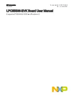


J1 (USB MCU-LINK)
J2 (USB ext. supply)
J3 (USB target MCU)
J19 (CAN)
J5 (Audio in)
J6 (Audio out)
JP3 (UART)
J44 (Audio expansion)
J102
J132
J92
J122
J8 (mikroBUS)
J7 (mikroBUS)
J41 (Ext. DMIC)
J38 (SWD)
SW1 (Wake-up)
SW3 (User)
SW2 (Reset)
D4
D5
D16 D18 D17
D15
D20
D14
(Motor 2 + Arduino)
(Motor 2 + Arduino)
Figure 2. LPC55S36-EVK connectors, push buttons, and LEDs (top-side view)
The figure below shows the bottom-side view of the LPC55S36-EVK board, with four connectors and one LED highlighted.
NXP Semiconductors
LPC55S36-EVK Overview
LPC55S36-EVK Board User Manual, Rev. 1, 24 January 2022
User Manual
9 / 49