


FBE clock mode. The MCG must not be configured in a clock mode where selected IRC
ATM clock is used to generate the system clock. The bus clock is also required to be
running with in the range of 8–16 MHz.
To perform the ATM on the selected IRC, the ATM machine uses the successive
approximation technique to adjust the IRC trim bits to generate the desired IRC trimmed
frequency. The ATM SARs each of the ATM IRC trim bits starting with the MSB. For
each trim bit test, the ATM uses a pulse that is generated by the ATM selected IRC clock
to enable a counter that counts number of ATM external clocks. At end of each trim bit,
the ATM external counter value is compared to the ATCV[15:0] register value. Based on
the comparison result, the ATM trim bit under test will get cleared or stay asserted. This
is done until all trim bits have been tested by ATM SAR machine.
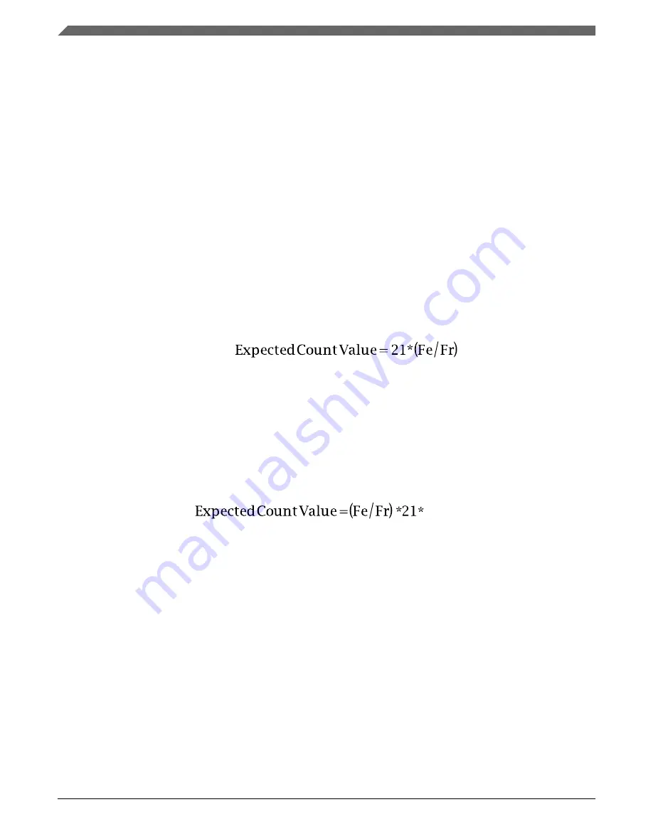
Before the ATM can be enabled, the ATM expected count needs to be derived and stored
into the ATCV register. The ATCV expected count is derived based on the required
target Internal Reference Clock (IRC) frequency, and the frequency of the external
reference clock using the following formula:
ATCV
• Fr = Target Internal Reference Clock (IRC) Trimmed Frequency
• Fe = External Clock Frequency
If the auto trim is being performed on the 4 MHz IRC, the calculated expected count
value must be multiplied by 128 before storing it in the ATCV register. Therefore, the
ATCV Expected Count Value for trimming the 4 MHz IRC is calculated using the
following formula.
(128)
25.5 Initialization / Application information
This section describes how to initialize and configure the MCG module in an application.
The following sections include examples on how to initialize the MCG and properly
switch between the various available modes.
25.5.1 MCG module initialization sequence
The MCG comes out of reset configured for FEI mode.
Initialization / Application information
K22F Sub-Family Reference Manual, Rev. 4, 08/2016
564
NXP Semiconductors
Содержание K22F series
Страница 2: ...K22F Sub Family Reference Manual Rev 4 08 2016 2 NXP Semiconductors...
Страница 150: ...Private Peripheral Bus PPB memory map K22F Sub Family Reference Manual Rev 4 08 2016 150 NXP Semiconductors...
Страница 168: ...Module clocks K22F Sub Family Reference Manual Rev 4 08 2016 168 NXP Semiconductors...
Страница 198: ...Security Interactions with other Modules K22F Sub Family Reference Manual Rev 4 08 2016 198 NXP Semiconductors...
Страница 258: ...Functional description K22F Sub Family Reference Manual Rev 4 08 2016 258 NXP Semiconductors...
Страница 292: ...Functional description K22F Sub Family Reference Manual Rev 4 08 2016 292 NXP Semiconductors...
Страница 398: ...Functional description K22F Sub Family Reference Manual Rev 4 08 2016 398 NXP Semiconductors...
Страница 628: ...Initialization and application information K22F Sub Family Reference Manual Rev 4 08 2016 628 NXP Semiconductors...
Страница 740: ...Initialization Application Information K22F Sub Family Reference Manual Rev 4 08 2016 740 NXP Semiconductors...
Страница 750: ...Functional description K22F Sub Family Reference Manual Rev 4 08 2016 750 NXP Semiconductors...
Страница 816: ...Application information K22F Sub Family Reference Manual Rev 4 08 2016 816 NXP Semiconductors...
Страница 866: ...Initialization Application Information K22F Sub Family Reference Manual Rev 4 08 2016 866 NXP Semiconductors...
Страница 890: ...Application information K22F Sub Family Reference Manual Rev 4 08 2016 890 NXP Semiconductors...
Страница 1028: ...Initialization Procedure K22F Sub Family Reference Manual Rev 4 08 2016 1028 NXP Semiconductors...
Страница 1040: ...Example configuration for chained timers K22F Sub Family Reference Manual Rev 4 08 2016 1040 NXP Semiconductors...
Страница 1118: ...Device mode IRC48 operation K22F Sub Family Reference Manual Rev 4 08 2016 1118 NXP Semiconductors...
Страница 1122: ...USB Voltage Regulator Module Signal Descriptions K22F Sub Family Reference Manual Rev 4 08 2016 1122 NXP Semiconductors...
Страница 1180: ...Initialization application information K22F Sub Family Reference Manual Rev 4 08 2016 1180 NXP Semiconductors...
Страница 1302: ...Application information K22F Sub Family Reference Manual Rev 4 08 2016 1302 NXP Semiconductors...
Страница 1374: ...Functional description K22F Sub Family Reference Manual Rev 4 08 2016 1374 NXP Semiconductors...