


M5251C3 Evaluation Board Users Guide, Rev. 0
Freescale Semiconductor
1-3
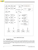
The MCF5251 processor has 128 Kbytes of internal SRAM organized as 2 banks of 64 Kbytes. The
SRAM can be used for either data or instruction space.
There is one SDRAM (U12) device on the PCB. The system ships with 1 x 4 Mbytes x 16 of SDRAM
totalling 8 Mbytes of volatile memory.
The internal cache of the MCF5251 is non-blocking. The instruction cache is 8 Kbytes with a 16-byte line
size. The ROM Monitor currently does not utilize the cache, but programs downloaded with the ROM
Monitor can initialize and use the cache.
1.3
Serial Communication Channels
The MCF5251 processor has 3 built-in UARTs with independent baud rate generators. The signals of all
channels can be passed through the external transceiver to make the channels RS-232 compatible (P4). An
RS-232 serial cable with DB9 connectors is included with the board. UART0 channel is the “TERMINAL”
channel used by dBUG for communication with an external terminal/PC. The “TERMINAL” baud rate
defaults to 19200.
1.4
Parallel I/O Ports
The MCF5251 offers up to 60 lines of general-purpose I/O, of which 6 are dedicated inputs and 3 are
dedicated outputs. Seven of the GPIO lines are also available as edge-sensitive interrupt inputs. In
addition, there is one dedicated input for wake-up from low-power mode.
1.5
System Configuration
The M5251C3 board requires the following items for minimum system configuration:
•
The M5251C3 board (provided)
•
Power supply, +7 V to 14 V DC with minimum of 1.0 amp
•
RS232C-compatible terminal or a PC with terminal emulation software
•
RS232 communication cable (provided)
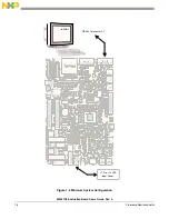
Refer to
Section 2.2.2, “System Initialization
displays the minimum system configuration.
Содержание freescale M5251C3
Страница 1: ...Document Number M5251C3UG Rev 0 05 2006 M5251C3 Evaluation Board Users Guide ...
Страница 6: ...M5251C3 Evaluation Board Users Guide Rev 0 vi Freescale Semiconductor ...
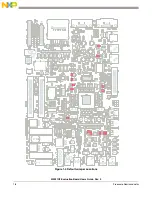
Страница 14: ...M5251C3 Evaluation Board Users Guide Rev 0 1 8 Freescale Semiconductor Figure 1 4 Default Jumper Locations ...
Страница 18: ...M5251C3 Evaluation Board Users Guide Rev 0 1 12 Freescale Semiconductor ...
Страница 42: ...M5251C3 Evaluation Board Users Guide Rev 0 2 24 Freescale Semiconductor ...
Страница 68: ...M5251C3 Evaluation Board Users Guide Rev 0 B 6 Freescale Semiconductor ...