


M5251C3 Evaluation Board Users Guide, Rev. 0
Freescale Semiconductor
3-9
3.6
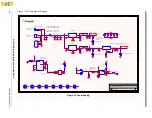
Flash Memory Card/IDE Interface Module
The SCF5251 memory bus allows connection of an IDE hard disk drive or SmartMedia flash card with a
minimum of external hardware. It can interface with both an IDE device and a SmartMedia device
connected, although both cannot be supported simultaneously, as the IDE-DIOR and IDE-DIOW signals
can only be used to interface to one or the other.
For further details, see the
MCF5251 Reference Manual
.
3.7
ATA Interface Module
The MCF5251 processor’s ATA Interface module includes the following features:
•
Programmable timing on the ATA bus. The interface works with wide range of bus frequencies.
•
Compliance with ATA-6 specification
— Support for PIO modes 0, 1, 2, 3, and 4
— Support for multiword DMA modes 0, 1, and 2
— Support for ultra DMA modes 0, 1, 2, 3, and 4 with bus clock of at least 50 MHz
— Support for ultra DMA mode 5 with bus clock of at least 80 MHz
•
128-byte FIFO part of interface
•
FIFO receive alarm and FIFO transmit alarm to DMA unit
•
Zero-wait cycles transfer between DMA bus and FIFO, which allows fast FIFO reading and
writing
For further details, see the
MCF5251 Reference Manual
.
3.8
Real-Time Clock (RTC) Module
The MCF5251 processor's RTC module is a mixed-signal circuit that provides an indicator of time (in
seconds) for various purposes in the system. The MCF5251 processor’s RTC module includes the
following features:
•
32.768 kHz crystal
•
Independent power supply pins to allow battery backup operation
•
Circuitry to detect power supply tampering
For further details, see the
MCF5251 Reference Manual
.
3.9
Debug Connector J12
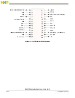
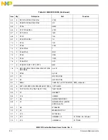
The MCF5251 processor has a Background Debug Mode (BDM) port, which supports Real-Time Trace
Support and Real-Time Debug. The signals which are necessary for debug are available at connector (J12).
shows the (J12) connector pin assignment.
Содержание freescale M5251C3
Страница 1: ...Document Number M5251C3UG Rev 0 05 2006 M5251C3 Evaluation Board Users Guide ...
Страница 6: ...M5251C3 Evaluation Board Users Guide Rev 0 vi Freescale Semiconductor ...
Страница 14: ...M5251C3 Evaluation Board Users Guide Rev 0 1 8 Freescale Semiconductor Figure 1 4 Default Jumper Locations ...
Страница 18: ...M5251C3 Evaluation Board Users Guide Rev 0 1 12 Freescale Semiconductor ...
Страница 42: ...M5251C3 Evaluation Board Users Guide Rev 0 2 24 Freescale Semiconductor ...
Страница 68: ...M5251C3 Evaluation Board Users Guide Rev 0 B 6 Freescale Semiconductor ...