


M5251C3 Evaluation Board Users Guide, Rev. 0
1-6
Freescale Semiconductor
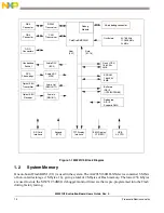
1.6.3
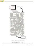
Providing Power to the Board
The board accepts three means of power supply connection—P1, P2, or J4. Connector P1 is a 2.1 mm
power jack, P2 is a lever-actuated connector, and J4 is a PC disk drive-type power connector. The board
a7 V to +14 V DC at 1.0 amp via either of the connectors.
connections on P2.
1.6.4
Selecting Terminal Baud Rate
The serial channel UART0 of the MCF5251 is used for serial communication and has a built in timer. This
timer is used by the dBUG ROM monitor to generate the baud rate used to communicate with a serial
terminal. A number of baud rates can be programmed. On power-up or manual RESET, the dBUG ROM
monitor firmware configures the channel for 19200 baud. Once the dBUG ROM monitor is running, a SET
command may be issued to select any baud rate supported by the ROM monitor. See
” for the discussion of this command.
1.6.5
Terminal Character Format
The character format of the communication channel is fixed at power-up or RESET. The default character
format is 8 bits per character, no parity and one stop bit with no flow control. It is necessary to ensure that
the terminal or PC is set to this format.
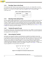
1.6.6
Connecting the Terminal
The board is now ready to be connected to a PC/terminal. Use the RS232 serial cable to connect the
PC/terminal to the M5251C3 PCB. The cable has a 9-pin female D-sub terminal connector at one end and
a 9-pin male D-sub connector at the other end. Connect the 9-pin male connector to connector P4 on the
M5251C3 board. Connect the 9-pin female connector to one of the available serial communication
channels normally referred to as COM1 (COM2, etc.) on the PC running terminal emulation software. The
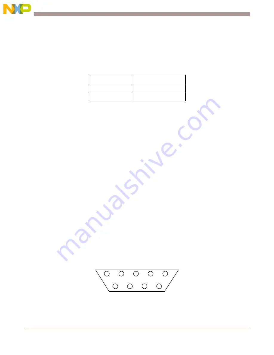
connector on the PC/terminal may be either male 25-pin or 9-pin. It may be necessary to obtain a
25pin-to-9pin adapter to make this connection. If an adapter is required, refer to
, which shows
the pin assignment for the 9-pin connector on the board.
Figure 1-3 Pin Assignment for Female (Terminal) Connector
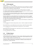
Table 1-1 Power Supply Connections on P2
Contact Number
Voltage
1
+7 V to +14 V DC
2
Ground
1
6
9
5
Содержание freescale M5251C3
Страница 1: ...Document Number M5251C3UG Rev 0 05 2006 M5251C3 Evaluation Board Users Guide ...
Страница 6: ...M5251C3 Evaluation Board Users Guide Rev 0 vi Freescale Semiconductor ...
Страница 14: ...M5251C3 Evaluation Board Users Guide Rev 0 1 8 Freescale Semiconductor Figure 1 4 Default Jumper Locations ...
Страница 18: ...M5251C3 Evaluation Board Users Guide Rev 0 1 12 Freescale Semiconductor ...
Страница 42: ...M5251C3 Evaluation Board Users Guide Rev 0 2 24 Freescale Semiconductor ...
Страница 68: ...M5251C3 Evaluation Board Users Guide Rev 0 B 6 Freescale Semiconductor ...