


NXP Semiconductors
KTFRDMHB2001FEVMUG
FRDM-HB2001FEVM evaluation board
KTFRDMHB2001FEVMUG
All information provided in this document is subject to legal disclaimers.
© NXP B.V. 2016. All rights reserved
User guide
Rev. 1.0 — 25 May 2016
26 / 35
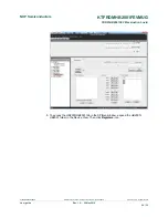
Stop
:
•
Press
Stop
to deactivate the outputs
Current Feedback
:
•
Shows current through the high-side FET using the current recopy feature
Status Fault
:
•
Shows any fault condition in Sleep mode
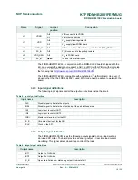
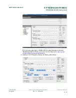
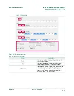
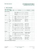
Table 11. Logic behind direction control with High-side versus Low-side recirculation
Half-Bridge Mode
Forward - High-side Recirculation
1
IN1 = 1
IN2 = PWM signal with selected duty cycle and frequency
Reverse - High-side Recirculation
2
IN1 = PWM signal with selected duty cycle and frequency
IN2 = 1
Forward - Low-side Recirculation
3
IN1 = PWM signal with selected duty cycle and frequency
IN2 = 0
Reverse - Low-side Recirculation
4
IN1 = 0
IN2 = PWM signal with selected duty cycle and frequency
H-Bridge Mode
Forward - High-side Recirculation
1
IN1 = 1
IN2 = PWM signal with selected duty cycle and frequency
Reverse - High-side Recirculation
2
IN1 = 0
IN2 = PWM signal with selected duty cycle and frequency