


NXP Semiconductors
KTFRDMHB2001FEVMUG
FRDM-HB2001FEVM evaluation board
KTFRDMHB2001FEVMUG
All information provided in this document is subject to legal disclaimers.
© NXP B.V. 2016. All rights reserved
User guide
Rev. 1.0 — 25 May 2016
19 / 35
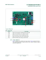
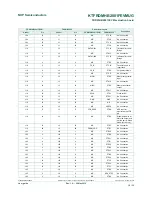
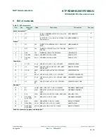
FRDM-HB2001FEVM
FRDM-KL25Z
Pin hardware name
Header
Pin
Header
Pin
FRDM-HB2001FEVM
FRDM-KL25Z
Description
J25
4
J9
4
N/C
P3V3
No Connection
J25
5
J9
5
N/C
PTB10
No Connection
J25
6
J9
6
N/C
RESET/PTA20
No Connection
J25
7
J9
7
N/C
PTB11
No Connection
J25
8
J9
8
N/C
P3V3
No Connection
J25
9
J9
9
N/C
PTE2
No Connection
J25
10
J9
10
N/C
P5V_USB
No Connection
J25
11
J9
11
N/C
PTE3
No Connection
J25
12
J9
12
GND
GND
Ground
J25
13
J9
13
N/C
PTE4
No Connection
J25
14
J9
14
GND
GND
No Connection
J25
15
J9
15
N/C
PTE5
No Connection
J25
16
J9
16
VDD_REG
P5-9V_VIN
5.0 V logic input
to FRDM-KL25Z
board from FRDM-
HB2001FEVM
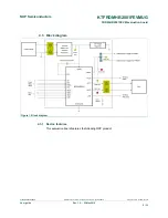
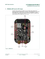
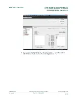
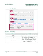
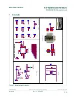
6 Installing the software and setting up the hardware
6.1 Configuring the hardware
The FRDM-HB2001FEVM consists of an H-Bridge, a parallel and SPI interface, power
conditioning circuitry and an FRDM-KL25Z board. The board can be configured for use in
conjunction with a FRDM-KL25Z board or a function generator.
Caution
When using the FRDM-HB2001FEVM, make sure that the maximum motor supply voltage (VPWR) stays
within the 5.0 V to 40 V range. Operating outside this range may cause damage to the board.
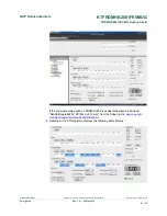
6.1.1 Step-by-step instructions for setting up the hardware for use with a FRDM-
KL25Z
To configure the FRDM-HB2001FEVM for use with the FRDM-KL25Z do the following:
1. Connect the FRDM-HB2001FEVM to the FRDM-KL25Z using the Arduino
™
connectors on each board.
2. Connect the USB cable (not supplied with the kit) between the PC and the KL25Z
USB port on the FRDM-KL25Z board.
3. With the power switched off, attach the DC power supply to the VBAT and GND screw
connector terminal (J20) on the evaluation board.
4. Connect the load to the screw terminal (J21).
Figure 13
illustrates the hardware configuration using a FRDM-KL25Z.