


Installing the software and setting up the hardware
FRDM-HB2001-EVM evaluation board
, Rev. 1.0
24
NXP Semiconductors
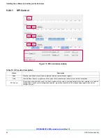
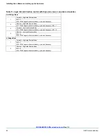
Table 11. Logic behind direction control with High-side versus Low-side recirculation
Half-Bridge Mode
1
Forward - High-side Recirculation
IN1 = 1,
IN2 = PWM signal with selected duty cycle and frequency
2
Reverse - High-side Recirculation
IN1 = PWM signal with selected duty cycle and frequency, IN2 = 1
3
Forward - Low-side Recirculation
IN1 = PWM signal with selected duty cycle and frequency, IN2 = 0
4
Reverse - Low-side Recirculation
IN1 = 0,
IN2 = PWM signal with selected duty cycle and frequency
H-Bridge Mode
1
Forward - High-side Recirculation
IN1 = 1,
IN2 = PWM signal with selected duty cycle and frequency
2
Reverse - High-side Recirculation
IN1 = 0,
IN2 = PWM signal with selected duty cycle and frequency