


Installing the software and setting up the hardware
FRDM-HB2001-EVM evaluation board
, Rev. 1.0
18
NXP Semiconductors
5
Installing the software and setting up the hardware
5.1
Configuring the hardware
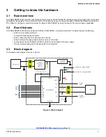
The FRDM-HB2001-EVM consists of an H-Bridge, a parallel and SPI interface, power conditioning circuitry and an FRDM-KL25Z board.
The board can be configured for use in conjunction with a FRDM-KL25Z board or a function generator.
Caution:
When using the FRDM-HB2001-EVM, make sure that the maximum motor supply voltage (VPWR)
stays within the 5.0 V to 40 V range. Operating outside this range may cause damage to the board.
5.1.1
Step-by-step instructions for setting up the hardware
for use with a
FRDM-KL25Z
To configure the FRDM-HB2001-EVM for use with the FRDM-KL25Z do the following:
1.
Connect the FRDM-HB2001-EVM to the FRDM-KL25Z using the Arduino™ connectors on each board.
2.
Connect the USB cable (not supplied with the kit) between the PC and the KL25Z USB port on the FRDM-KL25Z board.
3.
With the power switched off, attach the DC power supply to the VBAT and GND screw connector terminal (J20) on the
evaluation board.
4.
Connect the load to the screw terminal (J21).
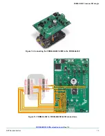
illustrates the hardware configuration using a FRDM-KL25Z.
Figure 14. FRDM-HB2001-EVM Configured for Use with an FRDM-KL25Z Board
FRDM-KL25Z Board
FRDM-HB2001-EVM
Brushed DC Motor
5 - 40 V Power Supply, 20 A
Workstation
Standard A to Mini-B
USB Cable
USB