


43
21. 07. 20. Document Number 671954
Nuaire |
Western Industrial Estate
|
Caerphilly
|
CF83 1NA
|
nuaire.co.uk
XBC+ with Ecosmart Connect (C) Control
Installation Manual
9.0 SA Bus Devices
9.1 Room Module
Room Modules are electronic, wall-mountable sensors designed to
work directly with the Nuaire control panel.
Room modules are automatically detected and require no set-up. The
majority of RM modules monitor room temperature; however, options
are available to also monitor zone humidity, carbon dioxide (CO2),
local temperature setpoint adjustments, PIR, and other variables. This
data is transmitted to a controller on the Sensor Actuator (SA) Bus.
58
59
SA Bus Devices
SA Bus Devices
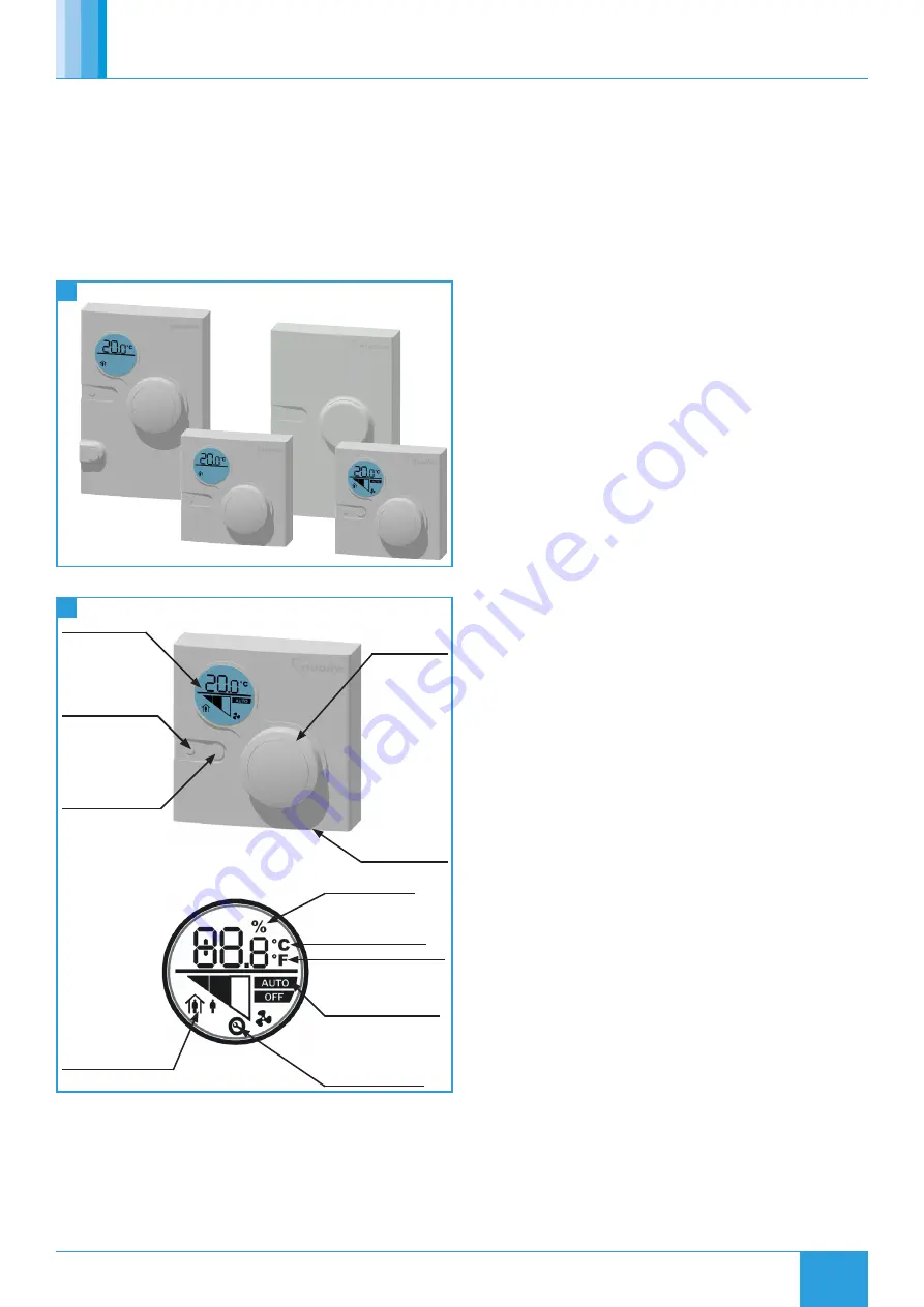
9.2 Features
LCD Display
Setpoint Adjust
Service Port
°F/°C Toggle
(some models)
Fan Speed Override/
Relative Humidity
(some models)
Occupied/
Unoccupied Mode
Loss of Network
Connection Symbol
Fan Mode (AUTO-OFF,
Low, medium, high)
Fahrenheit Temperature
Celsius Temperature
Relative Humidity
9.2.1 Backlit LCD Display
All LCD display versions of Room Modules include a dial to adjust
room setpoint. While the setpoint is being adjusted the backlight will
switch on and the display will update to show the setpoint. While
inactive the display will revert to display the current room temperature.
The occupancy status is also displayed on the LCD. On fan speed
override models the fan speed and override status is also displayed. A
maintenance icon will display if there is a sensor network error.
9.2.2 Service Port
A RJ12 service port is provided at the base of each Room Module. This
allows the temporary connection of an extra module to the sensor
network.
9.2.3 Fan Speed Override / Relative Humidity
This button cycles through fan speed override settings.
9.2.4 Room Humidity
The ESC-RM-2-TDH-120 model includes a push button on the face of
the network sensor to allow occupants to view the temperature and
relative humidity of the zone. Pressing the push button toggles between
temperature and RH on the LCD. The LCD defaults to temperature 5
seconds after the push button is released. Following this procedure to
permanently change the default display:
•
If the display backlight is off, press and release the push button
to illuminate the backlight. If the display backlight is already on,
proceed to Step 2.
•
Press and hold the push button for 5 seconds to switch to the
desired default display (either temperature or RH). Note: The
desired default display will flash for 5 seconds. After the display
stops flashing, the new default display is in effect.
•
Release the push button; the desired display is now the new
default display.
The humidity setpoint cannot change via RM sensors. This must be
changed through a commissioning tool.
9.3 Sensor Installation
Location considerations when locating the network sensor:
•
On a partitioning wall, approximately 5 ft (1.5m) above the floor
in a location of average temperature.
•
Away from direct sunlight, radiant heat, outside walls, outside
doors, air discharge grills, or stairwells; and from behind doors.
•
Away from steam or water pipes, warm air stacks, unconditioned
areas (not heated or cooled), or sources of electrical interference.
9.3.1 Removing Sensor Rear Cover
•
Use a Pozi screwdriver to loosen the screw on the top of the unit.
•
Insert a coin into the slot next to the security screw location,
pressing the tab that keeps the unit closed. Then carefully pry the
top edge of the sensor assembly away from its mounting base and
remove.
9.3.2 Modular Jack
For the modular jack, simply snap the wiring plug into the jack. A
modular jack requires a straight-through, one-to-one connection (not a
crossover). See interconnection section for details.


