NTI UNIMUX MULTI-USER KVM SWITCH
17
USING THE NTI UNIMUX USB KVM SWITCH
Basic Operation
The UNIMUX switch enables a user or several users to access any CPU at any time. A CPU can be shared so that more than
one user can use a CPU and work on the same project – each from their own console. Resolution is 2048x1536 with no
degradation –
guaranteed
. The front panel LCD indicates the port to which each user is attached. The UNIMUX can be
controlled by four methods:
•
keypad control
with LCD via front panel
•
OSD control
via the user devices (applicable only to models with video support)
•
RS-232 control
(see page 38)
•
Telnet Interface
- via command line interface (page 44)
Keypad Control
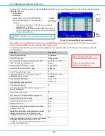
The front panel keypad and LCD (see Figure 15) display allow the user to monitor switch status and route any user to any CPU on
the switch. Along with the routing of the CPUs to the user devices the keypad and LCD allow the users to configure the RS-232
control interface. The keypad buttons perform the following functions:
Key
Action
ESC
Escape back to the main display.
0 – 9
Used to enter numbers. (
n
)
USR
The user device number can be entered (2 digits or 1 digit and ENTER)
followed by the desired CPU to be connected to.
CPU
Used following single digit user entries.
ENTER
Used following single digit entries.
Display next 4 users and the CPUs they are connected to. (See note below.)
Display previous 4 users and the CPUs they are connected to. (See note below.)
MENU
The RS-232 menu is displayed. This allows the baud rate to be set at 1200,2400,4800,9600,19200,
38400,57600, or 115200 baud and the unit address to be set to 1 - 15. See RS-232 control on page 38.
* Activate Memory Function- 10 memory locations (0 – 9), 0 is the power ON default.
to
Save
current
connections
*
- USR -
n (0-9) -
ENTER
to Recall connections
*
- CPU -
n (0-9) -
ENTER
to set all outputs to one input
*
-
n (0-9)
- ENTER
Note: By default, the display will show all connections between CPUs and users, displaying 4 at a time, from the first to
the last, and repeating the cycle indefinitely. If the user presses either the up or down arrow to manually view
connections, the display will freeze on the chosen view. To resume the default cycle of displaying all connections, the
user must press and hold either the up or down arrow for 3 seconds, and then release it.
The following examples show various methods of routing user 3 to CPU 5. CPUs and users can be entered as a two digit number
or a one digit number followed by ENTER.
USR - 3 - CPU - 5 - ENTER
USR - 3 - ENTER - 5 - ENTER
USR - 0 - 3 - 0 - 5
0 - 3 - 0 - 5
Figure 15- LCD display and keypad
1
2
3
CPU
4
5
6
USR
7
8
9
0
*
ESC
ENTER
MENU
USR: 1 2 3 4
CPU: 1 2 3 4


