


N1200HC Controller
NOVUS AUTOMATION
9/12
ktyp
Hardware Type - Parameter that informs the
controller about the hardware optionals installed. It
should not be altered by the user, except when an
accessory is introduced or removed
0
– Basic model. Without optional items.
1
– 485
Pas.(
Password - Allows defining a new access
password, always different from zero.
Prot
Protection - Sets up the Level of Protection. See
Table 6
.
Freq
Frequency - Mains frequency. This parameter is
important for proper noise filtering.
CONFIGURATION PROTECTION
The controller allows protecting the configuration setting made by the
user, preventing non unexpected modifications. The parameter
Protection (
PROt
), in the
Calibration Level
, determines the protection
strategy, limiting the access to particular levels, as shown by the
table below.
Protection
level
Protected levels
1
Only the Calibration level is protected.
2
I/Os and Calibration levels.
3
Tuning, I/Os and Calibration levels.
4
Alarm, Tuning, I/Os and Calibration levels.
5
Programs, Alarm, Tuning, I/Os and Calibration levels.
6
Tuning, Programs, Alarm, Input, I/Os and Calibration levels.
7
Operation (except SP), Tuning, Programs, Alarm, input, I/Os
and Calibration levels.
8
Operation, Tuning, Programs, Alarm, Input, I/Os and
Calibration levels.
Table 7
– Levels of Protection for the Configuration
ACCESS PASSWORD
The protected levels, when accessed, request the user to provide the
Access Password
for granting permission to change the
configuration of the parameters on these levels.
The prompt
PASS
precedes the parameters on the protected levels.
If no password is entered, the parameters of the protected levels can
only be visualized.
The Access Code is defined by the user in the parameter
Password
Change
(
PAS.(
), present in the Calibration level. The factory default
for the password code is 1111.
PROTECTION OF THE ACCESS CODE
The protection system built into the controller blocks for 10 minutes
the access to protected parameters after 5 consecutive frustrated
attempts of guessing the correct password.
MASTER PASSWORD
The Master Password is intended for allowing the user to define a
new password in the event of it being forgotten. The Master
Password doesn’t grant access to all parameters, only to the
Password Change parameter (
PAS(
). After defining the new
password, the protected parameters may be accessed (and
modified) using this new password.
The master password is made up by the last three digits of the serial
number of the controller
added
to the number 9000.
As an example, for the equipment with serial number 07154321, the
master password is 9 3 2 1.
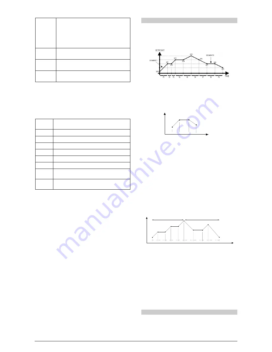
PROGRAMS OF RAMP AND SOAK
This feature allows the creation of a behavior profile for the process.
Each profile is built by up to
9 segments
and is named RAMPS AND
SOAKS PROGRAM and is defined by setpoint values and time
intervals. Up to
20 different profiles
can be programmed. The figure
below shows a program model:
Figure 8
- Ramp and Soak example
Once a profile is defined and selected for execution, the controller
starts to generate the SP profile automatically in accordance with the
elaborated program.
To execute a profile with fewer segments just program 0 (zero) for
the time intervals that follow the last segment to be executed.
SP
Time
T1
T2
T3
SP0
SP1
SP2
SP3
T4=0
Figure 9
- Program example with few segments
The program tolerance feature “
PtoL
” defines the maximum
admitted deviation of PV with respect to SP. If exceeded, the
program execution is suspended (the internal timer freezes) until the
deviation is back within the defined tolerance (SP is the priority). The
value 0 (zero) disables this functionality (program runs regardless of
the difference between PV and SP).
LINK
OF PROGRAMS
It is possible to create a more complex program, with up to 180
segments, joining the 20 programs. This way, at the end of a
program execution the controller immediately starts to run the next
one, as indicated in the “
LP
".
To force the controller to run a given program or many programs
continuously, it is only necessary to link a program to itself or the last
program to the first.
SV
Time
T1
T2
T3
T4
T5
T1
T2
T3
T4
SP0
SP1
SP2
SP3
SP4
SP5 / SP0
SP1 SP2
SP3
SP4
Program 1
Program 2
Figure 10
- Example of interlinked programs
EVENT ALARM
The Event Alarm function associates the alarms to specific segments
of a program.
To operate this feature, the alarms to be activated should have their
function defined as
rS
in the
PE1
to
PE9
parameters.
Notes
:
1 - Before starting the program, the controller waits PV to reach the
initial setpoint ("
SP0
").
2- Should any power failure occur, the controller resumes the program
execution at the beginning of the segment that was interrupted.
DETERMINATION OF PID PARAMETERS
The determination (or tuning) of the PID control parameters in the
controller can be carried out in an automatic way and auto-adaptative
mode. The
automatic tuning
is always initiated under request of the
operator, while the
auto-adaptive tuning
is initiated by the controller
itself whenever the control performance becomes poor.