


N1200HC Controller
NOVUS AUTOMATION
4/12
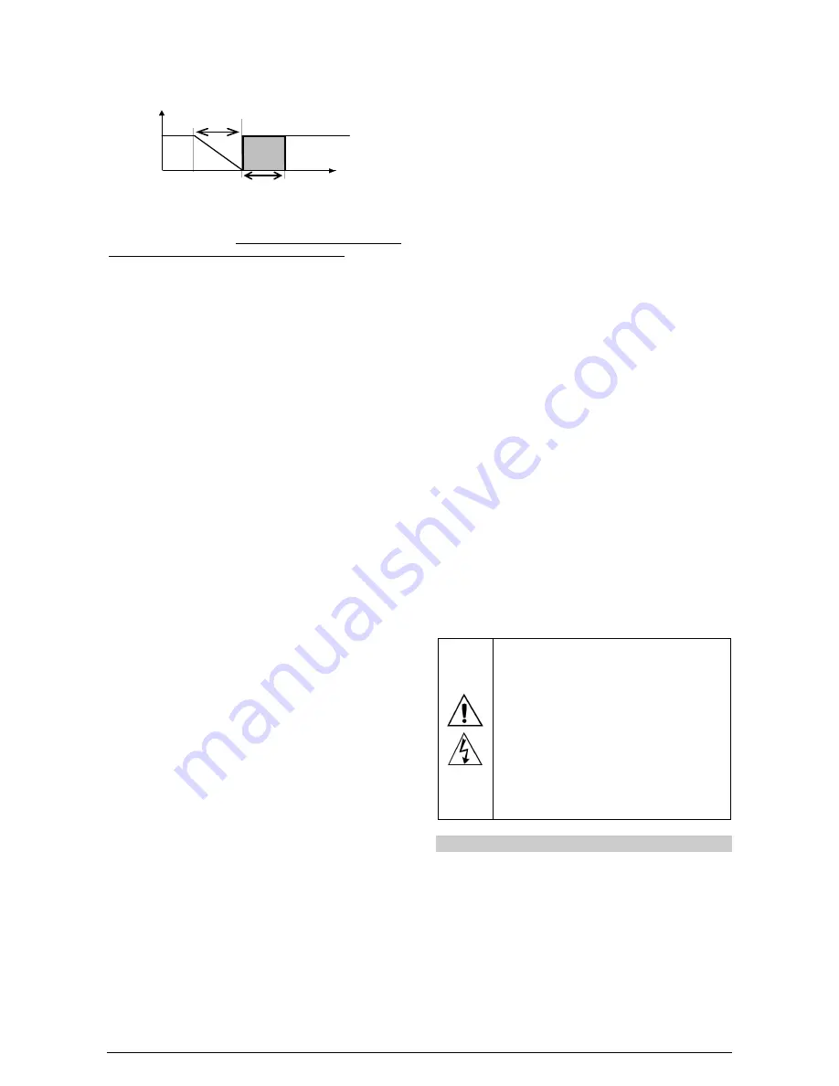
The proportional band 2 (Pb2) and the level time of PWM 2 (Ct2) are
independent. Here you must set the minimum and maximum power
for control 2.
Control Output
Process Variable
Pb1
Hst 2
Output 1
Output 2
OFF
ON
Set Point
RUN
MODE
The RUN parameter (
rvn
) operates as a master switch of the
controller outputs channels. It enables either the channels set to
control output as the defined as an alarm output. When this
parameter is settled to
YES
, the control outputs and alarm are able to
operate on and off in accordance to the determinations of the
controller. When it is settled to
NO
, all outputs remain off, regardless
of the needs of the process. In this condition, the display of the
controller shows a
STOP
message alternately with the measured
temperature value (PV).
ANALOG RETRANSMISSION OF PV AND SP
The analog output (available in I/O5), when not used for control
purposes, is available for retransmitting the PV and SP values in 0-
20 or 4-20 mA. This analog output is electrically isolated from other
inputs and outputs. The analog output signal is scalable, with the
output range defined by the values programmed in the parameters
“
rtLL
” and “
rtkL
”.
To obtain a voltage output, the user must install a resistor shunt
(550
Ω
max.) to the current output terminals (terminals 7 and 8).
The actual resistor value depends on the desired output voltage span.
SOFT-START
The soft-start feature avoids abrupt variations in the power delivered
to the load regardless of the system power demand.
This is accomplished by defining a limiting ramp for the control
output. The output is allowed to reach maximum value (100 %) only
after the time programmed in the soft-start parameter has elapsed.
The Soft-start function is generally used in processes that require slow
start-up, where the instantaneous application of 100 % of the available
power to the load may cause damages to parts of the system.
In order to disable this function, the soft-start parameter must be
configured with 0 (zero).
REMOTE SETPOINT
The controller can have its Setpoint value defined by an analog,
remotely generated signal. This feature is enabled through the
channels I/O3, I/O4 or I/O5 when configured as digital inputs and
configured with the function
rsp
(Remote SP selection) or through
the parameter
E.rsp
. The remote setpoint input accepts the signals
0-20 mA, 4-20 mA, 0-5 V and 0-10 V.
For the signals of 0-20 and 4-20 mA, a shunt resistor of 100
Ω
is
required between terminals 9 and 10, as shown in
Figure 4c
.
LBD - LOOP BREAK DETECTION
The parameter defines a time interval, in minutes, within which the
PV is expect to react to a control output signal. If the PV does not
react properly within the time interval configured in
lbd.t
, the
controller interprets this as a control loop break and signals this
occurrence in the display.
A LBD event may be sent to any I/O channel. Simply configure the
LDB
function to the desired I/O channel: the selected output will be
activated when a
LDB
condition is detected. When the
lbd.t
parameter is programmed with 0 (zero), the
LDB
function is disabled.
The
LDB
is useful in system supervision and troubleshooting, allowing
early detection of problems in the actuator, power source or load.
SAFE OUTPUT VALUE WITH SENSOR FAILURE
A function that sets the
control output 1
in a safe condition for the
process when is identified an error in the input sensor.
When the controller identifies a failure in the sensor (input), it forces
the value of MV1 applying the percentage set by the user in
parameter
1E.ov
.
If the
1E.ov
parameter is set to 0 (zero) this function will be disabled
and the control output will be simply switched off when sensor failure
occurs.
USB INTERFACE
The USB interface is used for CONFIGURING or MONITORING the
controller. The
NConfig
software must be used for the configuration.
It makes it possible to create, view, save and open configurations
from the equipment or files in your computer. The tool for saving and
opening configurations in files makes it possible to transfer
configurations between pieces of equipment and to make backup
copies. For specific models, the
NConfig
software also makes it
possible to update the firmware (internal software) of the controller
through the USB.
For MONITORING purposes you can use any supervisory software
(SCADA) or laboratory software that supports the MODBUS RTU
communication on a serial communications port. When connected to
the USB of a computer, the controller is recognized as a conventional
serial port (COM x). Use the
NConfig
software or consult the
DEVICE MANAGER in the Windows CONTROL PANEL to identify
the COM port that was assigned to the controller. Consult the
mapping of the MODBUS memory in the controller’s communications
manual and the documentation of your supervisory software to
conduct the MONITORING process.
Follow the procedure below to use the USB communication of the
equipment:
•
Download the
NConfig
software from our website and install it on
your computer. The USB drivers necessary for operating the
communication will be installed together with the software.
•
Connect the USB cable between the equipment and the
computer. The controller does not have to be connected to a
power supply. The USB will provide enough power to operate the
communication (other equipment functions cannot operate).
•
Open the
NConfig
software, configure the communication and
start recognition of the device.
The USB interface IS NOT SEPARATE from the
signal input (PV) or the controller digital inputs and
outputs. It is intended for temporary use during
CONFIGURATION and MONITORING periods. For
the safety of people and equipment, it must only be
used when the piece of equipment is completely
disconnected from the input/output signals. Using
the USB in any other type of connection is possible
but requires a careful analysis by the person
responsible for installing it. When MONITORING for
long periods of time and with connected inputs and
outputs, we recommend using the RS485 interface,
which is available or optional in most of our products.
INSTALLATION / CONNECTIONS
The controller must be fastened on a panel, following the sequence
of steps described below:
•
Prepare a panel cut-out of 45.5 x 45.5 mm;
•
Remove the mounting clamps from the controller;
•
Insert the controller into the panel cut-out;
•
Slide the mounting clamp from the rear to a firm grip at the panel.