Novus N1200HC Скачать руководство пользователя страница 5

N1200HC Controller 

NOVUS AUTOMATION 

5/12 

RECOMMENDATIONS FOR THE INSTALLATION 


The wires of the input signals must be disposed separated of the 

power and outputs wirings, if possible, in grounded ducts. 


All electronic instruments must be powered by a clean mains 

supply, proper for instrumentation. 


It is strongly recommended to apply RC'S FILTERS (noise 

suppressor) to contactor coils, solenoids, etc. 


In any application it is essential to consider what can happen when 

any part of the system fails. The controller features by themselves 

can not assure total protection. 

ELECTRICAL CONNECTIONS 

The controller's internal circuits can be removed without undoing the 

connections on the back panel. 
The controller complete set of features is drawn in 

Figure 1


Figure 1

 - Connections of the back panel 

Power Supply Connections 


Observe the power 

requirement for the 

unit. of required power 

supply 


Figure 2

 – Power supply connections 

Input Connections 


Thermocouple (T/C) and 0-50 mV 

The 

Figure 3a

 indicates the wiring for the thermocouple and 0-50mV 

signals. If the thermocouple wires needs  to be extended, use 

appropriate compensation cables. 


RTD (Pt100): 


Figure 3b

 shows the Pt100 wiring, for 3 conductors. For proper cable 

length compensation, use conductors of same gauge and length). 

For 4-wires Pt100, leave one conductor disconnected at the 

controller. For 2-wire Pt100, short-circuit terminals 11 and 12. 


T/C, 0-50mV


Pt100


Figure 3a

 - Connection of T/C, 0-

50mV 

Figure 3b

 - Connection of three wire 

Pt100 


4-20 mA: 

The connections for current signals 4-20 mA must be carried-out 

according to 

Figure 4a


4-20mA


Figure 4a

 - Current connection  

4-20 mA 

Figure 4b

 - Connection for 5 V and  


10 V 


5 V and 10 V 

Refer to 

Figure 4b

 for connecting voltage signals. 
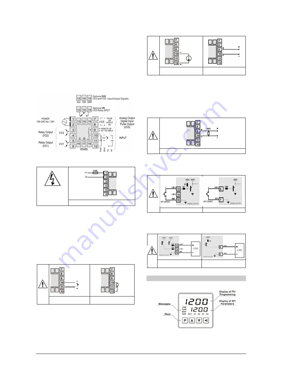
Remote Setpoint 

Feature available in the controller's terminals 9 and 10. When the 

Remote SP input signal is 0-20 mA or 4-20 mA, an external 

100 


shunt resistor of must be connected to terminals 9 and 10 as 

indicated in 

Figure 4c


Figure 4c

 - Connection for remote SP 

Digital Input Connections 

To use the I/O channels I/O 3, I/O 4 or I/O 5 as Digital Inputs connect 

a switch (Dry Contact) at its terminals. 


Figure 5a

 – I/O3 a Digital Input 

Figura 5b

 – I/O5 a Digital Input 

Connection of Alarms and Outputs 

The I/O channels, when configured as outputs, must have their load 

limit capacities observed, according to the product specifications. 


Figure 6a

 – I/ O3 or I/O4 with output 

pulse for SSR. 

Figure 6b

 –


I/O5 with output pulse 

for SSR. 

OPERATION 

The controller's front panel, with its parts, can be seen in the 

Figure 7


Figure 7

 - Identification of the parts referring to the front panel 

Содержание N1200HC

Страница 1: ...asic version with functions of minimum maximum differential deviation open sensor and event Timer functions that can be associated to the alarms Retransmission of PV or SP in 0 20 mA or 4 20 mA Input for remote setpoint Digital input with 5 functions Programmable soft start 20 setpoint profile programs with 9 segments each with the ability to be linked together for a total of 180 segments Password...

Страница 2: ...as the control setpoint Available for I O5 or I O3 and I O4 when available Closed remote SP Open uses main SP kprg Digital Input with Hold Program function Defines channel as Digital Input with the function of commanding the execution of the selected setpoint profile program Available for I O5 or I O3 and I O4 when available Closed Enables execution of the program Open Interrupts execution of the ...

Страница 3: ...n the controller is first energized The alarm will be enabled only after the occurrence of a non alarm condition followed by a new occurrence for the alarm The initial blocking is useful for instance when one of the alarms is configured as a minimum value alarm causing the activation of the alarm soon upon the process start up an occurrence that may be undesirable The initial blocking is disabled ...

Страница 4: ...ed The LDB is useful in system supervision and troubleshooting allowing early detection of problems in the actuator power source or load SAFE OUTPUT VALUE WITH SENSOR FAILURE A function that sets the control output 1 in a safe condition for the process when is identified an error in the input sensor When the controller identifies a failure in the sensor input it forces the value of MV1 applying th...

Страница 5: ...er cable length compensation use conductors of same gauge and length For 4 wires Pt100 leave one conductor disconnected at the controller For 2 wire Pt100 short circuit terminals 11 and 12 T C 0 50mV Pt100 Figure 3a Connection of T C 0 50mV Figure 3b Connection of three wire Pt100 4 20 mA The connections for current signals 4 20 mA must be carried out according to Figure 4a 4 20mA Figure 4a Curren...

Страница 6: ...ues are saved when the keys or are pressed after changing a parameter value The value of SP is saved upon pressing the key or every 25 seconds CONFIGURATION PARAMETERS OPERATION LEVEL PV AND SP INDICATION The upper display shows the current value of PV The lower display indicates the value of the control SP in automatic mode If PV exceeds the limits established or the input is open the upper displ...

Страница 7: ...unit of the input type If set a negative value the overlap shall be treated as dead band dead zone Lbd t Loop break detection time Time interval of the LBD function Maximum time interval for the response of PV to commands from the control output in minutes sfst SOFT START Time in seconds during which the controller limits the value of control output 1 progressively from 0 to 100 Starts when the co...

Страница 8: ...the MV Safe Output function is adopted If equal to 0 zero the function is disabled and the outputs turn off when a sensor failure occurs bavd Digital communication Baud Rate selection in kbps 1 2 2 4 4 8 9 6 19 2 38 4 57 6 and 115 2 prty Parity of the serial communication none Without parity Ewem Even parity 0dd Odd parity Addr Address Slave address selection Identifies the controller in the netwo...

Страница 9: ...last three digits of the serial number of the controller added to the number 9000 As an example for the equipment with serial number 07154321 the master password is 9 3 2 1 PROGRAMS OF RAMP AND SOAK This feature allows the creation of a behavior profile for the process Each profile is built by up to 9 segments and is named RAMPS AND SOAKS PROGRAM and is defined by setpoint values and time interval...

Страница 10: ...OFF an automatic tuning is immediately initiated by the controller if the controller is not in RUN YES the tuning will begin when it passes into this condition The accomplishment of this automatic tuning is essential for the correct operation of the auto adaptative tuning The methods of automatic tuning and auto adaptative tuning are appropriate for most of the industrial processes However there m...

Страница 11: ... improves the performance of the communication Terminal 18 CONFIGURATION OF PARAMETERS FOR SERIAL COMMUNICATION Two parameters must be configured for using the serial type bavd Communication speed prty Parity of the communication addr Communication address for the controller REDUCED REGISTERS TABLE FOR SERIAL COMMUNICATION COMMUNICATION PROTOCOL The MOSBUS RTU slave is implemented All configurable...

Страница 12: ...61326 1 1997 and EN 61326 1 A1 1998 SAFETY EN61010 1 1993 and EN61010 1 A2 1995 USB INTERFACE 2 0 CDC class virtual communications port MODBUS RTU protocol SPECIFIC CONNECTIONS FOR TYPE FORK TERMINALS OF 6 3 MM FRONT PANEL IP65 POLYCARBONATE UL94 V 2 CASE IP30 ABS PC UL94 V 0 STARTS UP OPERATION after 3 seconds connected to the power supply CERTIFICATIONS CE UL FILE E300526 IDENTIFICATION N1200HC ...

Отзывы: