N1050 Controller
NOVUS AUTOMATION
5/8
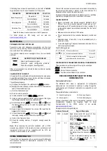
bL.a1
bL.a2
Blocking Alarm
Blocking Alarms.
YES
- Enables initial blocking;
No
- Inhibits initial blocking.
This parameter is not used for the alarm function
off
.
Hy.a1
Hy.a2
Histeresis of
Alarm
Defines the difference between the value of PV at
which the alarm is triggered and the value at which
it is turned off.
This parameter is not used for the alarm function
off
,
ierr
or
r5
.
fLsH
Flash
Allows visual signalization of an alarm occurrence
by flashing the indication of PV in the operation
level.
YES
- Enables alarm signaling flashing PV;
No
- Disables alarm signaling flashing PV.
This parameter is not used for the alarm function
off
.
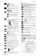
INPUT CYCLE
Type
Type
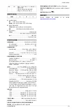
Input Type: Selects the input signal type to be
connected to the process variable input. Refer to
Table 01
for the available options.
(J):
Tc J
-110 to 950 °C / -166 to 1742 °F
(K):
Tc k
-150 to 1370 °C / -238 to 2498 °F
(T):
Tc t
-160 to 400 °C / -256 to 752 °F
(S):
Tc s
-50 to 1760 °C / -58 to 3200 °F
(Pt100):
Pt
-200 to 850 °C / -328 to 1562 °F
fLtr
Filter
Digital Input Filter. Used to improve the stability of
the measured signal (PV). The set value
corresponds to the value of the time constant. In
seconds (s). Adjustable from 0 to 300 s.
Dp.po
Decimal Point
Selects the decimal point position to be viewed in
both PV and SP.
uni t
Unit
Selects display indication for degrees Celsius or
Fahrenheit:
{C
- Indication in Celsius;
{f
- Indication in Fahrenheit.
Offs
Offset
Sensor Offset: Offset value to be added to the PV
reading to compensate sensor error.
Sp.LL
SP Low Limit
Defines the lower limit for adjustment of SP.
Sp.HL
SP High Limit
Defines the upper limit for adjustment of SP.
Lbdt
Loop break
detection time
Time interval for the LBD function. Defines the
maximum interval of time for the PV to react to a
control command. In minutes.
ie.ou
Input Error Output
Percentage value to be applied to the output on any
failure of the sensor that is connected to the
controller input.
Baud
Baud Rate
Baud rate of serial communication. Available in the
following baud rates (in kbps):
1.2, 2.4, 4.8, 9.6, 19.2, 38.4, 57.6 and 115.2
Prty
Parity
Parity of the serial communication.
NONE
- Without parity;
EVEM
- Even parity;
odd
- Odd parity.
Addr
Address
Number that identifies the controller in the serial
communication network, between 1 and 247.
CALIBRATION CYCLE
All types of input are calibrated in the factory. In case a
recalibration is required; it shall be carried out by a specialized
professional. In case this cycle is accidentally accessed, do not
perform alteration in its parameters.
Pass
Password
This parameter is presented before the protected
cycles. See item Protection of Configuration.
CaLb
Calibration
Enables the possibility for calibration of the
indicator. When the calibration is not enabled, the
related parameters are hidden.
in.LC
Input Low
Calibration
Enter the value corresponding to the low scale
signal applied to the analog input.
in.HC
Input High
Calibration
Enter the value corresponding to the full scale
signal applied to the analog input.
RESt
Restore
Restores the factory calibration for all inputs and
outputs, disregarding modifications carried out by
the user.
Cj
Cold Junction
This screen is for information purpose only.
This parameter is not used for the input function
type
Pt
.
Pas.C
Password Change
Allows defining a new access password, always
different from zero.
Prot
Protection
Sets up the Level of Protection. See
Table 03
.
H.PrG
Hold Program
Enables the
Hold Program
function on the key.
RUN.E
Run Enable
Enables the display of the RUN parameter on the
controller operating cycle.
SnH
Serial Number
High
Displays the first four digits of the electronic serial
number of the controller.
SnL
Serial Number
Low
Displays the last four digits of the electronic serial
number of the controller.
CONFIGURATION PROTECTION
The controller provides means for protecting the parameters
configurations, not allowing modifications to the parameters values,
avoiding tampering or improper manipulation. The parameter
Protection
(
Prot
), in the Calibration cycle, determines the
protection strategy, limiting the access to particular cycles, as shown
by the
Table 03
.
PROTECTION
LEVEL
PROTECTION CYCLES
1
Only the Calibration cycle is protected.
2
Input and Calibration cycles are protected.
3
Alarms, Input and Calibration cycles are
protected.
4
Programs, Alarms, Input and Calibration are
protected.
5
Tuning, Programs, Alarms, Input and
Calibration are protected.
6
All cycles, except SP screen in Operation
cycle, are protected.
7
All cycles, including SP, are protected.
Table 03
– Levels of Protection for the Configuration

