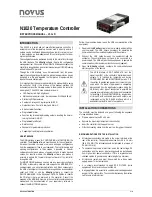
N1020 Temperature Controller
NOVUS AUTOMATION
3/8
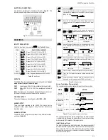
The initial blocking is useful, for instance, when one of the alarms is
configured as a minimum value alarm, causing the activation of the
alarm soon upon the process start-up, an occurrence that may be
undesirable.
The initial blocking is disabled for the sensor break alarm function.
RAMP AND SOAK FUNCTION
Allows reaching the SP value gradually. The value of SP is increased
gradually from an initial value (PV value) until it reaches the set
value. The
rate
parameter sets this increase for SP in degrees per
minute.
The Ramp function will work when turn on the controller, enable
control (RUN = YES) or when the SP value is changed. A value
equal to zero (0) in the rate parameter disables the Ramp function.
TIMER FUNCTION
The N1020 embeds a timer function (decreasing) for applications that
require particular process duration.
Once defined the time interval in the
T1me
parameter, the timer will
START when:
•
When PV reaches the temperature programmed in the SP
parameter.
•
When enabling the control (RUN = YES).
•
By pressing the F key when configured to Timer reset mode (the
timer is reloaded with the
T1me
parameter and restarts counting).
•
By pressing the F key in ON/OFF mode stops the timer counting;
pressing it again, resumes the counting.
When the timer expires, the two possible actions can be:
•
Disables de control (RUN→ NO) or
•
Activate the alarm.
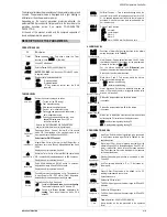
FUNCTIONS FOR THE F KEY
The F key on the frontal keypad is meant for special commands, as
follows:
•
Enable outputs (identically to the RUN parameter).
•
Timer reset: - reloads the timer and initiates a new time counting.
•
Timer ON/OFF. Timer holds or resumes counting each time the
F key is pressed.
Keeping the F key pressed for 3 seconds resets the timer
(reloads the timer to the value set in
T1me
), initiating a new time
counting.
Note: when the F key is configured as RUN = YES/NO (RUN =
f.key
), the controller outputs are born disabled after powers up.
SOFT-START
The Soft-start function is generally used in processes that require
slow start-up, where the instantaneous application of 100% of the
available power to the load may cause damages to parts of the
system.
In order to disable this function, the soft-start parameter must be
configured with 0 (zero).
OFFSET
Allows fine trimming the PV indication to compensate for sensor
errors. Default value: zero.
SERIAL COMMUNICATION
For full documentation download the Registers Table N1020 for
Serial Communication on our web site –
www.novusautomation.com
.
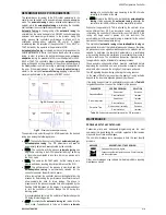
Fig. 02 – Serial Communications Conections
OPERATION
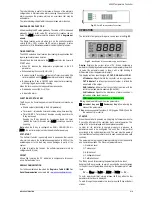
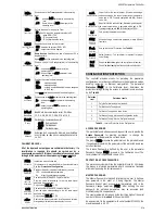
The controller’s front panel, with its parts, can be seen in the Fig. 03:
Fig. 03 - Identification of the parts referring to the front panel
Display: Displays the current value of PV. When configuring a
parameter, the display alternates between the parameter prompt and
its value (the parameter value is shown with a light blinking to
differentiate it from the parameter prompt).
The display contains also the signs AT, OUT, RUN ALM and COM:
AT Indicator: Stays ON while the controller is in tuning process.
OUT Indicator: For relay or pulse control output; it reflects the
actual state of the output.
RUN Indicator: Indicates that the controller is active, with the
control output and alarms enabled. (RUN=YES).
ALM Indicator: Signalize the occurrence of alarm condition. It
lights when either alarm is active.
COM Indicator: Flashes when there is RS485 activity.
P Key: Used to walk through the menu parameters.
Increment key and
Decrement key: allow altering the
values of the parameters.
F Key: accesses special functions: RUN (toggles YES/NO) and the
two modes of timer control.
STARTUP
When the controller is powered up, it displays its firmware version for
3 seconds, after which the controller starts normal operation. The
value of PV is then displayed and the outputs are enabled.
In order for the controller to operate properly in a process, its
parameters need to be configured first, such that it can perform
accordingly to the system requirements. The user must be aware of
the importance of each parameter and for each one determine a valid
condition.
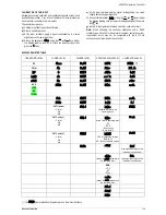
The parameters are grouped in levels according to their functionality
and operation easiness. The 5 levels of parameters are:
1 – Operation Level
2 – Tuning Level
3 – Alarms Level
4 – Configuration Level
5 – Calibration Level
The P key is used for accessing the parameters within a level.
Keeping the P key pressed, at every 2 seconds the controller jumps
to the next level of parameters, showing the first parameter of each
level:
PV >>
atvn
>>
fva1
>>
type
>>
pass
>> PV …
To enter a particular level, simply release the P key when the first
parameter in that level is displayed.
To walk through the parameters in a level, press the P key with short
strokes.

