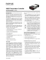
N1020 Temperature Controller
NOVUS AUTOMATION
2/8
ELECTRICAL CONNECTIONS
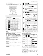
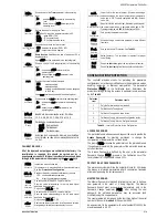
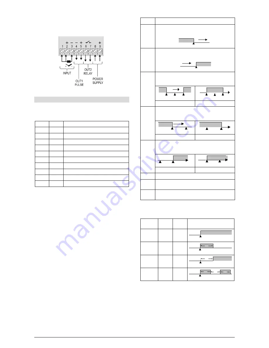
The controller complete set of features is drawn in Fig. 01. The
features loaded in a particular unit are shown on its label:
Fig. 01 - Connections of the back panel
FEATURES
INPUT TYPE SELECTION
Select the input type (in parameter “
tYPE
”) from Table 01 below.
TYPE
CODE
RANGE OF MEASUREMENT
J
Tc j
Range: -110 to 950 ºC (-166 to 1742 ºF)
K
Tc k
Range: -150 to 1370 ºC (-238 to 2498 ºF)
T
Tc t
Range: -160 to 400 ºC (-256 to 752 ºF)
N
Tc n
Range: -270 to 1300 ºC (-454 to 2372 ºF)
R
Tc r
Range: -50 to 1760 ºC (-58 to 3200 ºF)
S
Tc s
Range: -50 to 1760 ºC (-58 to 3200 ºF)
B
Tc b
Range: 400 to 1800 ºC (752 to 3272 ºF)
E
Tc e
Range: -90 to 730 ºC (-130 to 1346 ºF)
Pt100
Pt
Range: -200 to 850 ºC (-328 to 1562 ºF)
0 to 50 mV
L0.50
Linear. Programmable indication -1999 to 9999
Table 01 - Input Types
OUTPUTS
The N1020 offers two output channels, user configurable as Control
output, Alarm 1 output or Alarm 2 output.
OUT1 - Logical pulse, 5 Vdc / 25 mA, available at terminals 4 and 5.
OUT2 - Relay SPST-NA, 1.5 A / 240 Vac, available at terminals 6
and 7.
Note: The outputs can be configured independently from each other,
for example, both can be control outputs at the same time.
CONTROL OUTPUT
The control strategy can be configured as ON / OFF or PID.
ALARM OUTPUT
There two alarms available in the N1020. The alarms can be
assigned to either output, logical or relay. The alarm functions are
described below.
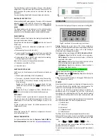
ALARM FUNCTIONS
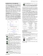
The alarms can be configured to operate with nine different functions,
as shown in Table 02.
off
Alarms turned
Off
.
lo
Alarm of Absolute Minimum Value. Triggers when the value of
measured PV is below the value defined for alarm Setpoint
(SPA1 or SPA2).
SPA1
PV
ki
Alarm of Valor Absolute Maximum Value. Triggers when the
value of measured PV is above the value defined for alarm
Setpoint.
SPA1
PV
dif
Alarm of Differential Value. In this function the parameters
SPA1
and
SPA2
represent the deviation of PV in relation to
the SP of CONTROL.
SP
PV
SP + SPA1
SP – SPA1
SP
PV
SV – SPA1
SV + SPA1
SPA1 positive
SPA1 negative
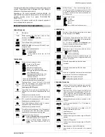
difl
Alarm of Minimum Differential Value. It triggers when the value
of PV is below the defined point by (using the Alarm 1 as
example):
SP
PV
SP – SPA1
SP
PV
SP – SPA1
SPA1 positive
SPA1 negative
difk
Alarm of Valor Maximum Differential Value. Triggers when the
value of PV is above the defined point by (using Alarm 1 as
example):
SP
PV
SP + SPA1
SP
PV
SP + SPA1
SPA1 positive
SPA1 negative
t.0n
Timer ON alarm. Sets alarm output ON when timer is runing.
t.end
Timer end. Configures the alarm to actuate when the timer
expires.
ierr
Sensor Break Alarm. Activated when the input signal of PV is
interrupted, out of the range or when Pt100 in short-circuit.
Table 02 – Alarm functions
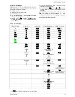
Alarms Timer Modes (Temporization)
The controller alarms can be configured to perform 4 timer modes:
MODE
A1t1
a2t1
A1t2
A2t2
ACTION
Normal
Operation
0
0
Alarm Event
Alarm
Output
Activation for
a defined time 1 to 6500 s
0
Alarm Event
Alarm
Output
T1
Activation with
delay
0
1 to 6500 s
Alarm Event
Alarm
Output
T2
Intermittent
Activation 1 to 6500 s 1 to 6500 s
Alarm Event
Alarm
Output
T1
T2
T1
Table 03 - Temporization Functions for the Alarms
The signs associated to the alarms will light when the alarm condition
is recognized, not following the actual state of the output, which may
be temporarily OFF because of the temporization.
Initial Blocking of Alarm
The initial blocking option inhibits the alarm from being recognized if
an alarm condition is present when the controller is first energized (or
after a transition from run YES
NO). The alarm will be enabled
only after the occurrence of a non alarm condition followed by a new
occurrence for the alarm.

