
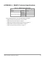


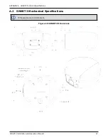
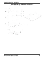
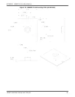
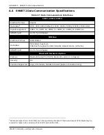
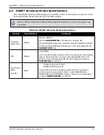

APPENDIX A SMART2 Technical Specifications
SMART2 Installation and Operation Manual 1
74
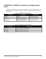
Signal Name
J1
J2
J3
J4
J5
E1
E2
COM2-TXD
3
2
COM2-RXD
4
3
COM3-TXD
8
2
COM3-RXD
13
3
CAN+
6
7
CAN-
7
2
SIGGND
5
5
SIGGND
5
5
SIGGND
5
5
SIGGND
5
3
SIGGND
5
SIGGND
EMD RADAR OUT (E2)
10
ER_OUT
RELAYO1/MARK INPUT (E2)
11
MKI
PPS/RLYO2 (E2)
12
PPS
PWR RET (GND) (E1)
9
BATT-
PWR INPUT (E1)
14
BATT+
CAN
SAE J1939/ ISO 11783/ ISO 11898 Compatible
PPS Output
3.3 V CMOS Logic Compatible
Ground Speed Output
High= Supply Voltage Maximum
Low= 1.5 V Maximum
Load= 3K Ohm Minimum
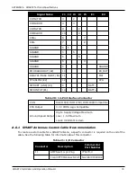
Table 20: 14-Pin Interface Connector
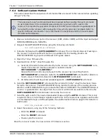
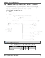
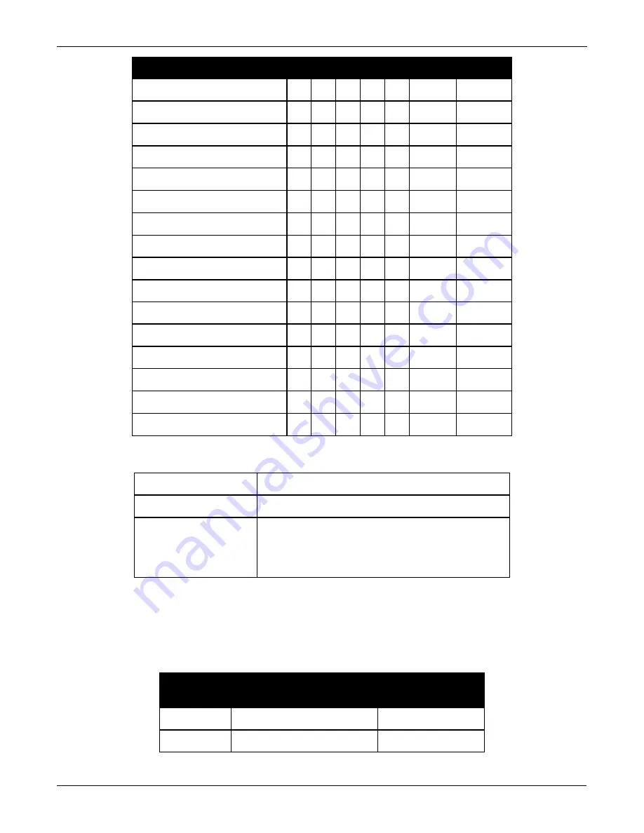
A.6.1 SMART Antennas Custom Cable Recommendation
To create a custom cable for a SMART Antenna, a specific connector is required on the end of the
cable. See the following table for information about this connector.
Connector
Description
Commercial
Part Number
J1
AMP Seal 14-pin Plug
776273-4
14-pin TYCO connector kit
NovAtel 01020132
Table 21: I/O Connector