


Chapter 2 SMART2 Installation
SMART2 Installation and Operation Manual 1
17
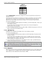
Port
RS-232
COM1
Yes
COM2
Yes
COM3
Yes
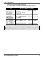
Table 5:
SMART2 Serial
Port Protocol
Use the
SERIALCONFIG
command to configure the receiver’s asynchronous serial port com-
munications drivers.
Port settings (bit rate and parity, for example) are software configurable. See
on page 21 for information about configuring the serial ports. Also see
SMART2 Data Communication Specifications
on page 71 for the serial port specifications.
To connect to a serial port:
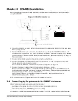
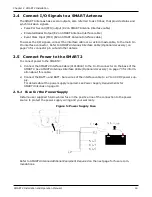
1. Connect the SMART2 Interface cable (PN: 01019944), or a custom made cable, to the 14-pin
Tyco Ampseal connector.
For information about the SMART2 interface cable refer to
2. Connect the appropriate DB9 connector (COM1, COM2 or COM3) to the serial port on the com-
puter or other data communication device.
2.3.2 CAN Bus Port
The SMART2 has a CAN Bus port available on the 14-Pin interface connector.
To connect to the CAN Bus port:
1. Connect the SMART2 optional accessory cable or a custom made cable, to the main 14-Pin
interface connector.
For information about the SMART2 interface cable, see
SMART Antennas Interface Cable
on page 73. This section also has the connector pin out and connector
recommendations for making a custom cable.
2. Connect the CAN to the CAN Bus (J5) of the SMART2 interface cable, see
Interface Cable (Optional Accessory)
The SMART2 CAN bus port is unterminated. If the SMART2 is at the end of the bus, then
the connecting cable must have 120 ohms integrated into the cable between CAN1+ and
CAN1- in close proximity to the main 14-Pin interface connector.
2.3.3 Bluetooth
Bluetooth is a wireless radio communication standard designed for use over short ranges (within
10 m). SMART2 receivers equipped with the Bluetooth hardware option support the Bluetooth
Classic SPP to provide a Bluetooth virtual serial port: COM6.