


Chapter 1 SMART2 Overview
SMART2 Installation and Operation Manual 1
12
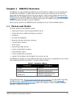
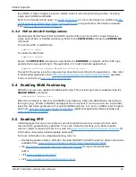
1.2 SMART2 Connector Overview
All SMART2 models use the same connector for power and communication. Refer to
below for pin outs.
Figure 1: SMART2 Interface Connector
Pin
Use
Pin
Use
1
COM1 TxD
8
COM3 TxD
2
COM1 RxD
9
Power Negative/Return
3
COM2 TxD
10
ER_OUT (Emulated Radar Output)
4
COM2 RxD
11
MKI (Mark Input)
5
Signal Ground (COM/MKI/PPS/ER)
12
PPS (Pulse Per Second) Output
6
CAN+
13
COM3 RxD
7
CAN-
14
Power Positive/Source
Table 2: SMART2 Connector Pin-out
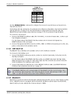
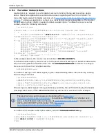
1.3 SMART2 LED
The SMART2 has a single LED to indicate status.
Figure 2: SMART2 Status LED
Label
Description
Model
Status (Power/GNSS)
All hardware options
Table 3: SMART2 Status Indicator