72
OEM6 Family Installation and Operation User Manual Rev 7
Chapter 5
Built-In Status Tests
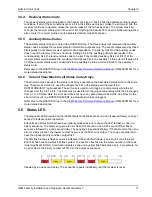
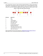
In the example shown in
Figure 27, Status LED Flash Sequence Example
, the first flash in
the sequence is red, meaning a bit is set in the receiver error word. The next five flashes give a binary
value of 00111. Converting this value to decimal results in a value of seven. Therefore, bit seven of the
receiver error word is set, indicating a problem with the supply voltage of the receiver’s power circuitry.
Figure 27: Status LED Flash Sequence Example
Reference Description
1
Red
2
Yellow
3
1 Second Pause
4
Word Identifier Flash
5
Bit Identifier Flashes
6
End of Sequence
7
End of Previous Sequence
8
Beginning of Sequence
9
Most Significant Bit of Binary Value
10
Least Significant Bit of Binary Value
11
Start of Next Sequence
Refer to the RXSTATUS log and associated tables in
OEM6 Family Firmware Reference Manual
(OM-20000129) for more information about this log and receiver error status.
...
...
1
1
1
2
2
1
1
1
1
3
4
5
6
7
8
9
10
11

