40
OEM6 Family Installation and Operation User Manual Rev 7
Chapter 3
Installation FlexPak6
3.3.4
Battery Backup
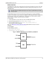
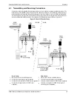
If installed in a vehicle so as to avoid loss of lock when tracking L-Band, it is recommended a back-up
battery be placed between the receiver and its voltage supply as a power buffer. When a vehicle engine
is started, power can dip to 9.6 V DC or cut-out to ancillary equipment causing the receiver to lose lock
and calibration settings.
3.3.5
FlexPak6 Status Indicators and Connector Labels
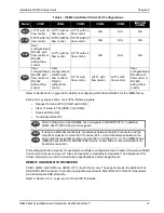
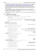
The following figure indicates the connector locations and the table identifies and defines the connectors.
Figure 16: FlexPak6 Connectors
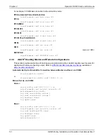
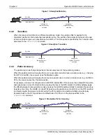
Table 5: FlexPak6 Status Indicators and Connector Labels
Vehicle Main
Battery
Auxiliary
Battery Isolator
from Vehicle
Alternator
to Vehicle Electrical
System
Battery
FlexPak6
Connector
Description
Antenna/
Position Valid
Solid
GREEN
with valid position
/
Solid
RED
indicates a board error
COM1
Flashing
GREEN
when transmitting data from COM1
/
Flashing
RED
when receiving
data on COM1
COM2
Flashing
GREEN
when transmitting data from COM2
/
Flashing
RED
when receiving
data on COM2
Power
Solid
RED
when voltage within the acceptable range is applied
I/O
Input and output port for additional signals such as Ethernet and CAN Bus signals
USB Communications port
COM 1
COM 2
I/O
Antenna
COM1 and COM2
Power
USB
Ethernet, CAN Bus and I/O

