134
OEM6 Family Installation and Operation User Manual Rev 7
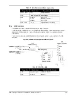
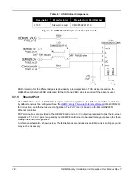
Table 27: USB Critical Components
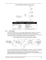
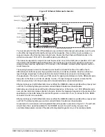
Figure 66: OEM628 USB Implementation Schematic
ESD protection for the differential pair is provided by a low capacitance TVS device located on the
OEM628 card. External ESD protection for the UID and VBUS pins is required if the pins are used.
C.1.5
Ethernet Port
The OEM628 provides a 10/100 Ethernet port with auto-negotiation. The Ethernet interface is disabled
by default and must be configured. See the
OEM6 Family Firmware Reference Manual
(OM-20000129)
for instructions on Ethernet device configuration. The PHY layer is based on the Micrel KSZ8851
Ethernet controller.
PHY terminations are provided on the OEM628 card and a 3.3 V output is presented to bias the Ethernet
magnetics. The 3.3 V power supplied by the OEM628 card is not to be used for any purposes other than
biasing the Ethernet magnetics.
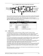
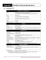
A reference schematic is shown below. The ferrite beads are included as an EMI de-risk contingency and
may not be necessary.
Designator
Manufacturer
Manufacturer Part Number
L100
Steward / Laird
CM0805C221R-10

