


148
OEM6 Family Installation and Operation User Manual Rev 7
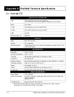
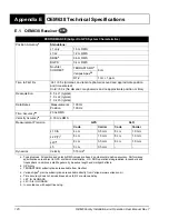
POWER REQUIREMENTS
Voltage
Normal Mode: +3.3 VDC +5%/-3%
OEMV3 Compatibility Mode (power via main header): +4.5 VDC to 36 VDC
For best performance, NovAtel strongly recommends additional supply
bypassing as close as possible to the OEM638 supply pins.
For the 3.3V supply - minimum 22 uF in parallel with 0.1 µF
For the wide-range supply - minimum 44 uF in parallel with 0.1 µF
Allowable Input Voltage Ripple 100 mV p-p maximum
Power Consumption
2.65 W typical, GPS L1/L2/GLONASS L1/L2/BDS B1/B2
2.8 W typical, GPS L1/L2
3.0 W typical, GPS/GLONASS L1/L2
3.1 W typical, GPS L1/L2/L5, GLONASS L1/L2, (without L-Band)
3.1 W typical, GPS L1/L2, GLONASS L1/L2 (with L-Band)
3.3 W typical, all on (without L-Band)
Power consumption values assume Ethernet is disabled. Ethernet
draws approximately 450 mW. If reduced power consumption is required, turn
off the Ethernet port as outlined in
“Chapter Ethernet Configuration” on page
and the
ETHCONFIG
command described in the
(OM-20000129)
The above values can change with the number of satellites in view and the
firmware version. Use only as a guide and not as absolute values
In-Rush Power Consumption 12.0 A for less than 60
s (typical)
Antenna Connector
MMCX female, 50
Acceptable RF Input Level
L1: -122 to -87 (signal) dBm, -161 to -141 (noise) dBm/Hz
L2: -126 to -93 (signal) dBm, -161 to -141 (noise) dBm/Hz
L-Band: -125 to -102 (signal) dBm, -161 to -151 (noise) dBm/Hz
L5/E5: -119 to -84 (signal) dBm, -161 to -141 (noise) dBm/Hz
RF Input Frequencies
GPS L1:
1575.42 MHz
Galileo E1:
1575.42 MHz
GPS L2:
1227.60 MHz
Galileo E5a:
1176.45 MHz
GPS L5:
1176.45 MHz
Galileo E5b:
1207.14 MHz
GLONASS L1:
1593-1610 MHz
Galileo E5:
1191.795 MHz
GLONASS L2:
1237-1253 MHz
L-Band:
1525 to 1560 MHz
Galileo E1:
1575.42 MHz
BeiDou B1:
1561.098 MHz
BeiDou B2:
1207.14 MHz
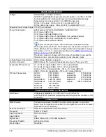
POWER REQUIREMENTS (CONTINUED)
LNA Power
Voltage user selectable: +3.3 VDC ±10% or +5 VDC ±10%
current 0-200 mA maximum (supplied by card through center conductor of RF
connector)
CONNECTORS
MMCX female
Connections between the MMCX and an external oscillator, or interface
board, must be impedance controlled. To accomplish this use 50 ohm coaxial
cable and 50 ohm connectors.
External Clock input
Refer to the EXTERNALCLOCK command
Frequency
5 MHz or 10 MHz
Input Impedance
50 Ohm nominal
Input VSWR
<2:1
Signal Level
0 dBm minimum to +13.0 dBm maximum
Frequency Stability
±0.5ppm maximum
Wave Shape
Sinusoidal