nosstec 8264 Скачать руководство пользователя страница 16

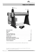
Operating instructiOns 8264

16


2018-09-12

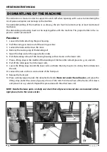
disManTlinG of The Machine

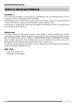
This instruction is made in order to support trained staff when repairing with a view to minimizing the 

risk of personal injuries and damage to the machine.
To enable dismantling of the machine in a safe way, the job must be carried out by at least two trained 

mechanics.
This dismantling instruction must not be kept together with the machine. The proper holder is the su-

pervisor and/or service staff.

Procedure:

1.  Loosen the bolts attaching the gear housing.
2.  Pull the worm gear motor out of the worm gear box.
3.  Loosen the bolts and remove the cover.
4.  Remove the locking ring of the bending roll.
5.  Open the drop end on the opposite drive side.
6.  Pull the bending roll out of the bearing housing so that it rests on the lower rolls.
7.  Place a lifting strap in the middle of the bending roll. Remove the roll and place it e.g. on a bench.
8.  Pull off the roller gears from the lower rolls.
9.  Lower the lifting strap around the lower rolls and fixate them by means of a strong flat iron between 

the rolls.

10. Loosen the nuts on the in- and outside of the front part.
11. Release the front part.
12. Place a strong support under the detached roll ends (Note: not under the roll necks), and place the 

lifting strap under the centre of gravity of one of the rolls. Pull the roll out of the frame, lift it down 

and place it on e.g. a bench. Repeat this procedure with the other lower roll.

NOTE: Handle the loose parts carefully and check that all pieces removed also are mounted in their 

right places, but in the reverse order.

5

6

11

10

1

3

7

4

10

Содержание 8264

Страница 1: ...Bending Roll Machine 8264 Operating Instructions...

Страница 2: ......

Страница 3: ...e plates and stickers 15 Dismantling of bending roll machine 16 Declaration of conformity 22 Contact information See back Note We reserve the right to alter specifications without prior notice For cop...

Страница 4: ...nding roll Lower roll Stand drop end Drop end Main components Front side Foot switch Disclaimer The machine pictured on this page is not necessarily representative of the actual product as delivered D...

Страница 5: ...up so that the workpiece can be introduced between the bending roll and lower rolls After having cen tered the workpiece in the machine the bending roll is screwed down towards the workpiece so that a...

Страница 6: ...wn the clamp and remove the workpiece Raise the clamp and mount the locking device Cone bending In order to be able to make cones the machine must be equipped with a cone bending device The cones are...

Страница 7: ...uctions This machine must be lifted by truck as long as it is packed in a crate or a wooden case When lifting it from the pack ing to the permanent working site an approved lifting de vice type travel...

Страница 8: ...mises is satisfactory The floor must be clean dry and free from oil and grease spots Never use easily inflammable material close to the machine Dirty working sites increase the risk of accidents Posit...

Страница 9: ...The instruction manual contains important information that besides the safety information also give important information regarding operation service maintenance etc Modification of the machine All c...

Страница 10: ...job begins If the machine must be dismantled completely or partly contact your foreman Protective clothing Important Never use gloves when bending as this consider ably increases the risk of getting...

Страница 11: ...operator has got the necessary information regard ing the safety of the machine as well as the special risks involved with this type of machine If the machine is not used in the proper way the manufa...

Страница 12: ...and oil level here Maintenance The machine is delivered with greased bearings for about 200 hours continuous duty After this period it should be lubricated with ball bearing grease of good quality e g...

Страница 13: ...nts 1 Front left side 1 points 2 Front right side 1 point 3 Rear left side 1 point 4 Rear right side 1 points See images for the lubrication points locations Oil points There are in total 4 locations...

Страница 14: ...weight kg Weight of rolls Bending roll kg m Lower rolls kg m Total dimensions length width height mm Working height mm Motor rating kW Voltage V Feeding motor Brand Type V kW Diameter of bending roll...

Страница 15: ...he machine with the top roll in swing out position White and yellow background black text White and yellow background black text White and yellow background black text Yellow background black text Yel...

Страница 16: ...osite drive side 6 Pull the bending roll out of the bearing housing so that it rests on the lower rolls 7 Place a lifting strap in the middle of the bending roll Remove the roll and place it e g on a...

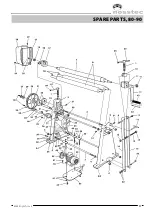
Страница 17: ...8264 English rev 3 17 Spare parts 80 90...

Страница 18: ...Operating Instructions 8264 18 2018 09 12 Spare parts 90 100...

Страница 19: ...8264 English rev 3 19 Spare parts 100 110...

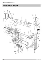
Страница 20: ...Operating Instructions 8264 20 2018 09 12 Spare parts 120 130...

Страница 21: ...30 1 Kugghjul Gear Zahnrad Roue dent e 31 1 Kugghjul Gear Zahnrad Roue dent e 32 3 Skruv Screw Schraube Vis 33 1 Drivaxel Drive shaft Antriebswelle Arbre de commande 34 1 Kil Wedge Keil Coin 35 1 Kug...

Страница 22: ...Manufacturer Nossebro Mekaniska Verkstad AB SE 465 30 NOSSEBRO 46 512 298 80 Distributor Nosstec AB SE 465 30 NOSSEBRO 46 512 298 85 herewith declare that Machine Type Serial No is manufactured in con...

Страница 23: ......

Страница 24: ...30 Nossebro SWEDEN Tel 46 0 512 298 85 Fax 46 0 512 298 89 E mail info nosstec se For copyright reasons all reproduction and copying of the texts tables and illustrations within this manual is prohibi...

Отзывы: