28
OM944F 5/21
SP-12. INJECTION PUMP
1. Since operating conditions may vary considerably, it
is difficult to give a definite interval for checking the
injection pump. But as a rule, pump settings,
maximum speed, and exhaust smoke should be
checked after every 2000 hours of operation.
Service of the fuel injection pump should only be
done if checks indicate pump malfunction.
2. Black smoke can be an indication of pump
malfunction. Before servicing the pump, check other
possible causes:
a. Check cleanliness of the air filter.
b. Check valve clearances.
c. Clean and check injectors.
3. Any repair which involves disassembly of the
injection pump must be carried out by specially
trained mechanics with the proper tools and test
equipment.
NOTE: All warranties on the engine become null
and void if the injection pump seals are
broken by unauthorized persons.
4. Injection Pump Removal:
CAUTION: Escaping diesel fuel under pressure
can have sufficient force to penetrate the skin,
causing serious personal injury. If injured by
escaping diesel fuel, see a doctor at once.
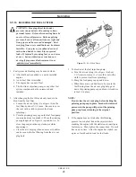
a. Clean the injection pump, hoses, and area
around the pump with a cleaning solvent or steam
cleaner.
NOTE: Never steam clean or pour cold water on an
injection pump while the engine is running
or the pump is warm.
b. Remove the injection lines from the
pump and injectors. Remove all lines as an
assembly. Do not remove the spacers. Cover the
ends of the lines, the injector inlets, and the
injection pump outlets to keep dirt out of the
injectors, lines, and pump.
Servicing
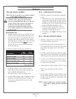
5. Injection Pump Installation:
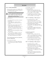
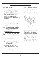
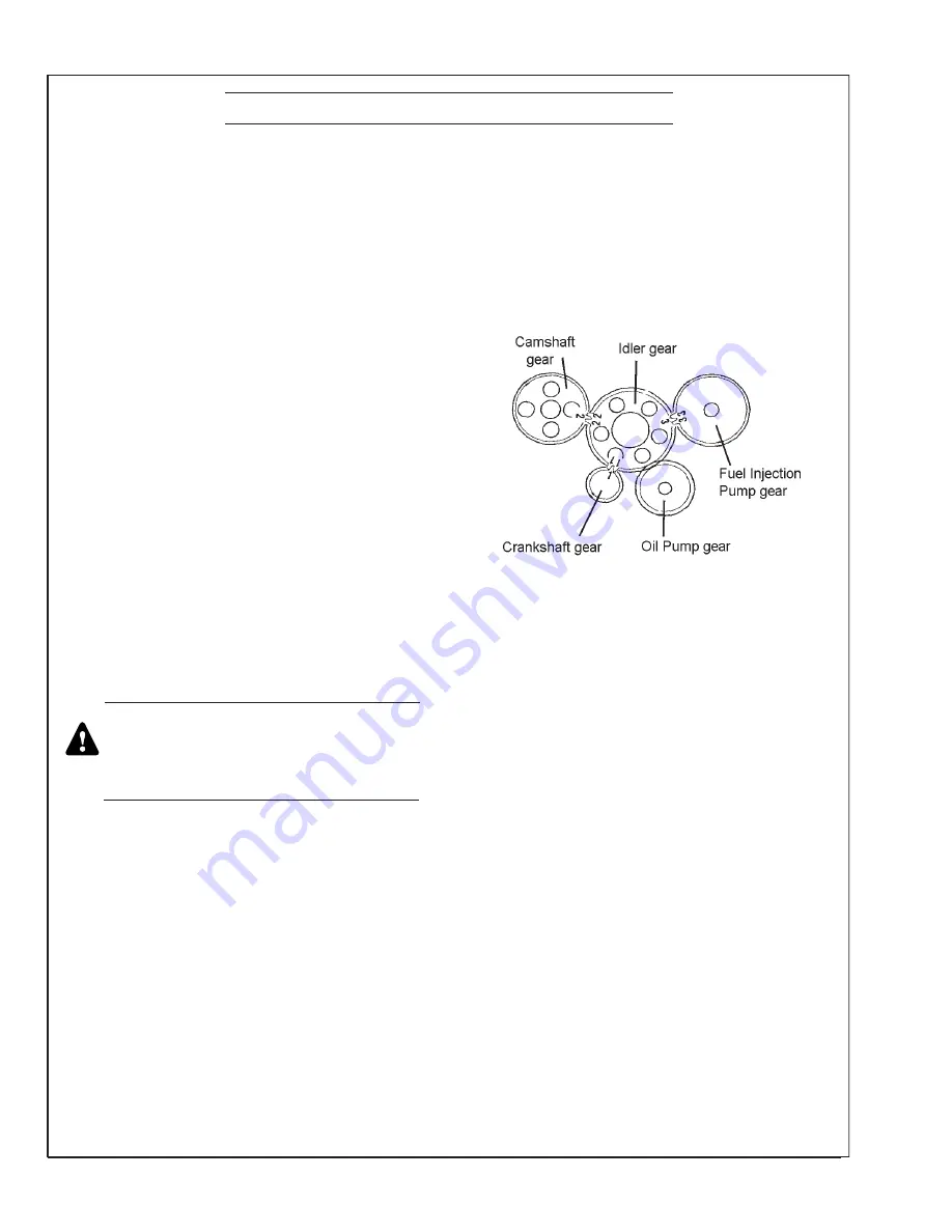
a. Install the fuel injection pump after having
aligned its gear alignment mark with that of
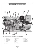
the idler gear alignment mark as shown in
Figure 11 above. When the alignment marks
of the timing gears align as in the diagram to
the right, the No. 1 piston is top dead center in
the compression stroke.
b.
Install the injection pump to the side of the
engine first then put in the end bolts, and
then the tube with its bolts, and then the side
bracket.
c. Torque mounting bolts to 13.0 - 18.1 ft/lbs
(17.7 to 24.5 N•m), 1.8 to 2.5 kgf•m.
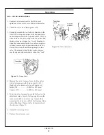
Figure 14
: Timing Marks
c. Remove the injection pump drive gear cover
plate and the sea water pump.
d. Align timing marks on timing gears.
e. Remove the pump support bracket on rear of
pump.
f. Remove the 4 mounting nuts.
g. Take the pump to your Northern Lights dealer or
an injection repair station for testing and service.
Содержание M944T3F
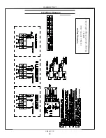
Страница 70: ...68 OM944F 5 21 Panel Wiring Diagram Panel Wiring Diagram S 1 Panel B A 12798B Updated 10 16 20...
Страница 71: ...OM944F 5 21 69 NORTHERN LIGHTS Panel Wiring Diagram Panel Wiring Diagram S 1B B Deutsch A 12791C...
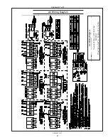
Страница 72: ...70 OM944F 5 21 NORTHERN LIGHTS Panel Wiring Diagram Panel Wiring Diagram S 3B S 3C Panel B A 12790D...
Страница 73: ...OM944F 5 21 71 Panel Wiring Diagram S 3A B Deutsch B 10854D Panel Wiring Diagram Updated 3 31 21...
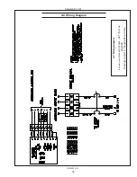
Страница 75: ...OM944F 5 21 73 NON CURRENT MODEL AC Wiring Diagram AC Wiring Diagram M944W3 and M30CW3 12 wire B 9723D...
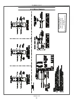
Страница 79: ...OM944F 5 21 77 DC Wiring Diagram DC Wiring Diagram M944W3 24 VDC Isolated Ground C 6871A NON CURRENT MODEL...
Страница 83: ......

