
OM944F 5/21
17
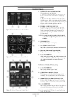
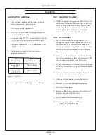
BEFORE STARTING
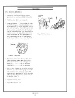
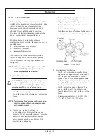
1. Check the water level by removing the pressure
cap from the expansion tank. In order to give the
cooling water an opportunity to expand, the level
should be about 1 in. (2.5 cm) below the filler cap
sealing surface when the engine is cold.
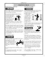
CAUTION: Use protective clothing and open
the filler cap carefully when the engine is warm
to prevent burns.
2. Check the oil level in the crankcase with the
dipstick. The oil level must be between high and
low marks on the stick. Never allow the level to go
below this area. Always add the same viscosity of
oil as is already in the crankcase.
3. Check the fuel tank level and open any fuel valves
on the tank and at the secondary fuel filter.
4. Close the sea-cock, check and clean the sea strainer,
and reopen the sea-cock.
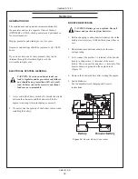
5. Place the battery switch in the ON position.
NOTE: The battery switch must always be kept ON
while the engine is running. If the switch is
turned OFF while the engine is running,
the battery charging alternator could be
damaged.
BREAK-IN PERIOD
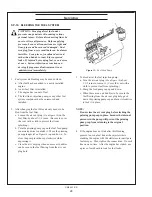
1. The first 100 hours on a new or reconditioned
engine are critical to its life and performance.
2. Operate engine under various conditions, particularly
heavy loading and minimal or no load conditions to
help seat engine components properly.
3. Constantly check the engine temperature and oil
pressure gauges.
4. Oil consumption is greater during break-in as
piston rings take time to seat.
5. Break-In Oil Changes: Change engine oil and
filter at 50 hours. Change oil and filter again at
100 hours (consult Lubricants section for oil
recommendation).
Operating Instructions:
Maintain at least a 75% load on your generator
set for the first 100 hours. If this is not possible,
maintain no less than a 50% load to ensure proper
seating of the piston rings. Vary the load to help
seat the rings.
Operating Procedures
Emission-Related Installation Instructions (For “F” Series Models)
Failing to follow these instructions when installing
a certified engine in a vessel violates federal law (40
CFR 1068.105(b)), subject to fines or other penalties as
described in the Clean Air Act.
The installed exhaust system should not create exhaust
back pressure greater than 15” (381 mm) of water,
measured at the engine exhaust elbow.
If you install the engine in a way that obscures the
engine’s emission control information label during
normal engine maintenance, you must place a duplicate
label on the vessel, as described in 40 CFR 1068.105.
Updated 11-10-20
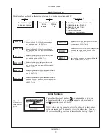
Содержание M944T3F
Страница 70: ...68 OM944F 5 21 Panel Wiring Diagram Panel Wiring Diagram S 1 Panel B A 12798B Updated 10 16 20...
Страница 71: ...OM944F 5 21 69 NORTHERN LIGHTS Panel Wiring Diagram Panel Wiring Diagram S 1B B Deutsch A 12791C...
Страница 72: ...70 OM944F 5 21 NORTHERN LIGHTS Panel Wiring Diagram Panel Wiring Diagram S 3B S 3C Panel B A 12790D...
Страница 73: ...OM944F 5 21 71 Panel Wiring Diagram S 3A B Deutsch B 10854D Panel Wiring Diagram Updated 3 31 21...
Страница 75: ...OM944F 5 21 73 NON CURRENT MODEL AC Wiring Diagram AC Wiring Diagram M944W3 and M30CW3 12 wire B 9723D...
Страница 79: ...OM944F 5 21 77 DC Wiring Diagram DC Wiring Diagram M944W3 24 VDC Isolated Ground C 6871A NON CURRENT MODEL...
Страница 83: ......


