24
OM944F 5/21
SP-6. VALVE CLEARANCES
1. Readjust valve clearance after first 50 hours of
operation. Check valves every 500 hours thereafter.
2. Check the valves when the engine is cold.
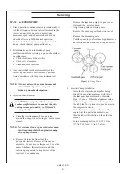
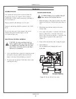
3. Rotate the crankshaft in a clockwise direction in the
front 180
0
to bring each piston to the top dead center
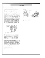
on the compression stroke. Top dead center (TDC) is
when notch on the pulley aligns with the pointer and
the two valves on cylinder No. 1“rock”. Rocking is
when the rocker arms (for the two valves on a given
cylinder) are moving in opposite directions, one up
closing the valve and one down opening the other
valve. The moment when the two rocker arms are
exactly aligned with each other is when they “rock”.
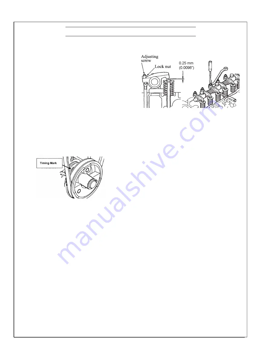
Figure 11:
Timing Mark
4. Measure the valve clearance for each of the valves,
with a feeler gauge, in the firing order (1-3-4-2).
Standard valve clearances for a cold engine are:
Intake (IN)........................0.0098 in. (0.25 mm)
Exhaust (EX)....................0.0098 in. (0.25 mm)
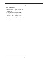
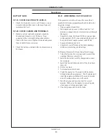
5. To adjust valve clearance, loosen the lock nut on the
adjustment screw. Insert a feeler gauge between the
rocker arm and the valve stem cap. Adjust, while
measuring the clearance, until the feeler gauge slides
with a slight drag. Tighten the lock nut and recheck
the clearance (Figure 9).
6. Adjust the remaining valves.
7. Replace the rocker arm cover.
Servicing
Figure 12:
Valve Adjustment
Содержание M944T3F
Страница 70: ...68 OM944F 5 21 Panel Wiring Diagram Panel Wiring Diagram S 1 Panel B A 12798B Updated 10 16 20...
Страница 71: ...OM944F 5 21 69 NORTHERN LIGHTS Panel Wiring Diagram Panel Wiring Diagram S 1B B Deutsch A 12791C...
Страница 72: ...70 OM944F 5 21 NORTHERN LIGHTS Panel Wiring Diagram Panel Wiring Diagram S 3B S 3C Panel B A 12790D...
Страница 73: ...OM944F 5 21 71 Panel Wiring Diagram S 3A B Deutsch B 10854D Panel Wiring Diagram Updated 3 31 21...
Страница 75: ...OM944F 5 21 73 NON CURRENT MODEL AC Wiring Diagram AC Wiring Diagram M944W3 and M30CW3 12 wire B 9723D...
Страница 79: ...OM944F 5 21 77 DC Wiring Diagram DC Wiring Diagram M944W3 24 VDC Isolated Ground C 6871A NON CURRENT MODEL...
Страница 83: ......

