20
Motor
Settings
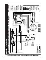
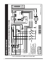
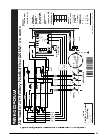
WIRING DI
AG
RAM
V
ariable
Speed
Air
Handler
High
Vo
ltag
e
Lo
w
Vo
ltage
High
Vo
ltag
e
F
actory Wiring
Field
Wirin
g
NO
TES:
1)
Not suitab
le f
or systems
ex
ceeding120V to ground
2) If an
y inter
nal wir
ing must be replaced, it must be
replaced with 105C wire of the same gauge
.
3)
When connecting accessor
ies to circuitboard,
remo
ve
the jumper supplied with the unit
.
4)
F
or A/C applications
, connect "O" to "Y".
1
2
3
5
4
GREEN
W2
W1
O
Y/Y2
G
R
C
24VAC
COM
TRANSFORMER
PO
WER SUPPL
Y
CUT
WIRES
TO
REMO
VE PLUG HOUSING
WHEN HEA
TER KIT IS
NO
T INST
ALLED
24V
WHITE
BL
AC
K
GREY
BL
AC
K
WHITE
MO
TO
R
1
2
3
5
4
6
7
8
9
10
11
12
13
14
15
16
1
2
3
5
4
6
7
8
9
10
11
12
13
14
15
16
1
2
3
5
4
6
7
8
9
10
11
12
13
14
15
16
ORANGE
WHITE
GRE
Y
RED
GREEN
WIRE
HARNESS
240/20
8
BL
OW
ER BO
AR
D
CONTR
OL BO
ARD
FUSE
1
2
3
5
4
6
7
8
9
10
11
12
13
14
15
16
GC
O
HUM
Y1
WR
HUM
Y/Y2
L2 COM 2
L2
L2COM
L1
VS POWER
XFMR
COOL
HEA T
Y1
HE
AT
ER PLUG
P3
12
3
4
5
6
78
YELL
OW
BLUE
RED
JUMPE
R
SELEC
TO
R SWITCHES
NO
TE
:
1 = ON
0 = OFF
710544D
(Replaces 710544C)
¢710544¬¤
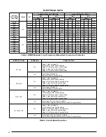
CFM
Switch
Number
A-Cabinet
B-Cabinet
C-Cabinet
12
34
540
720
1075
00
01
600
800
1225
00
00
660
880
1380
00
10
715
850
1135
10
01
790
945
1295
10
00
870
1040
1460
10
10
915
1085
1525
01
01
955
1140
1625
11
01
1015
1205
1740
01
00
1060
1325
1960
01
10
1075
1265
1860
11
00
1165
1390
2090
11
10
Nom.
KW
CFM
Switch
Number
A-Cabinet
B-Cabinet
C-Cabinet
56
0-5
700
700
-
00
0-
9-
-
700
00
6-9
800
--
10
6-10
-
800
-
10
10-14
950
--
01
10-14
--
950
10
11-15
-
950
-
01
15
110
0-
-
11
15-20
--
1100
01
16-20
-
110
0-
11
21-30
--
1500
11
Minim
um Electric Heat Air
-Flo
w
Del
ay
Desc
Switch
Number
78
Del
ay
A
00
Del
ay
B
01
No Del
ay
10
De-Hum
11
Del
ay
Settings
(all models)
(Modular blower supports 20kW heat max.)
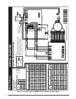
Figure 14. Wiring Diagram for B5BM Series Air Handler (Variable Speed)
Содержание B5BM
Страница 27: ...27...

