18
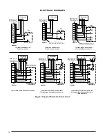
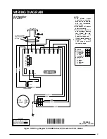
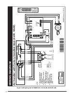
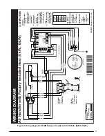
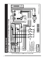
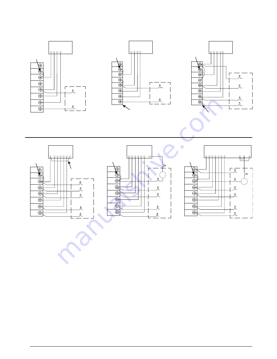
ELECTRICAL DIAGRAMS
Figure 12. Typical Thermostat Connections
G R
W2
C
E O Y
Thermostat
G R
W
Thermostat
Y
C
Y
G R
W
Thermostat
Y
C
Air
Handler
Air
Conditioner
Y
Typical Air Conditioner with
Standard Air Handler
G R C E
O Y
Thermostat
Typical Heat Pump w/Standard Air Handler
Typical Air Conditioner with
Variable Speed Air Handler
Typical Heat Pump with Optional Outdoor
Thermostat and Variable Speed Air Handler
NOTE: Jumper W1
&W2 together for
shorter staging time.
W2
W1
O
Y/Y2
G
R
C
W2
W1
O
Y/Y2
G
R
C
W2
W1
O
Y/Y2
G
R
C
W2
W1
O
Y/Y2
G
R
C
G R
W2
C
E O
Y1
Thermostat
OD
Stat
O
Y1
R
C
G R
W
Thermostat
Y1
C
Y1
W 2
E
Typical 2-Stage Air Conditioner
with Variable Speed Air Handler
Typical 2-Stage Cooling Heat Pump with
Optional Outdoor Thermostat &Variable
Speed Air Handler
W2
W1
O
Y/Y2
G
R
C
W2
W1
O
Y/Y2
G
R
C
Y2
Y2
Y2
Y2
W1
W3
R
Y1
Y1
Y1
Y1
Y1
Y1
Air
Conditioner
Air
Handler
NOTE: Jumper W1
&W2 together for
shorter staging time.
NOTE: Jumper W1
&W2 together for
shorter staging time.
NOTE: For AC applications, the O & Y
connection must be connected as shown.
Air
Conditioner
Air
Handler
NOTE: For AC applications, the O & Y
connection must be connected as shown.
Heat Pump
Air
Handler
NOTE: Jumper W1
&W2 together for
shorter staging time.
NOTE: Jumper W1
&W2 together for
shorter staging time.
NOTE: Jumper W1
&W2 together for
shorter staging time.
Heat Pump
OD
Stat
E
O
W 2
R
C
Y
Air
Handler
Air
Handler
W2
O
W 2
R
C
Y
Heat Pump
NOTE: Jumper between
W2 & E is required when
no OD T-Stat is used.
Содержание B5BM
Страница 27: ...27...

