22
BLOWER
MOTOR
PLUG
6
5
4
3
2
1
WIRING DIA
GRAM
710587B
(Replaces 710587A)
Air Handler with F
actory Installed Heat (8 kW, 10kW)
Legend
Field
Wiring
F
actory
Wiring:
Lo
w
Vo
ltag
e
High
Vo
ltag
e
W2
W1
O
Y/Y2
G
R
C
TRANSFORMER
24
V
BL
AC
K
RED
WHIT
E
BLA
CK
WHIT
E
FUSE
L2 COM 2
L2
L2 COM
L1
VS POWER
XFMR
COOL
HEA T
24 VA
C
RED
COM
GREY
P3
HEA
TER KIT
PLUG
Y1
NO
TES
1)
The blo
wer motor speed tap
connection ma
y not be as
sho
wn.
See the Installation
Instructions.
2) Disconnect all po
wer bef
ore
servicing.
3)
T
ransf
ormer ma
y ha
ve a dual
v
oltage primary tap.
Match the
tap position with the suppl
y
v
oltage used.
4)
If the Internal wiring is
replaced
,
use on
ly
105
°
C
copper wire of the same
gauge
.
3
2
1
6
5
4
7
BLACK
RED
ELEMENT
BLACK
GREY
BLACK
POWER
PLUG
LIMIT
RED
RED
RED
RED
RED
BLACK
RELAY
RELAY
TERMINAL
BLOCK
(f
or select
models onl
y
)
CIRCUIT
BREAKER
(Cir
cuit breaker
models only)
ELEMENT
4 SP
D.
MO
TO
R
1
2
3
5
6
4
1 = COM
2 = HIGH
3 = MED HIGH
4 = MED LOW
5 = LOW
6 = OPEN
BR
OW
N
1 = COM
2 = HIGH
3 = MED HIGH
4 = MED LOW
5 = LOW
6 = OPEN
GREY
BLUE
ORANGE
GREY
ORANGE
BLUE
¢710587D¤
BLACK
BLACK
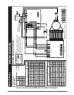
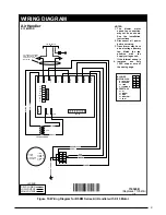
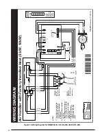
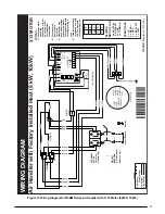
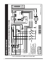
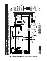
Figure 16. Wiring Diagram for B5BM Series Air Handler (8kW & 10 kW)
Содержание B5BM
Страница 27: ...27...


