About the Touch Screen Display and User Interface
4-5
Part 1120130
E
2011
Nordson Corporation
About the Operator Display
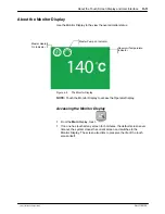
Use the Operator Display to manage zones and pumps, as well as access
the system Master Controls.
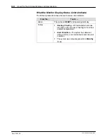
Color
Description
Main
Display
Monitor
Display
Anywhere on the display
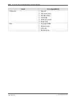
Touch any zone to:
*Enable/Disable
*Modify its setpoint
temperature
Touch any Pump to:
* Enable/Disable
* Adjust its RPM
* Modify its Operation Mode
Touch any Master Control
(Heaters, Pumps and Standby)
to switch them On/Off
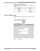
Figure 4‐3
The Operator Display
Содержание AltaBlue
Страница 8: ...Table of Contents vi Part 1120130 E 2011 Nordson Corporation...
Страница 9: ...1 Setting Up Inputs Outputs 3 18 Setting Up Gear to Line Operation 3 23...
Страница 22: ...TABSHEET Introduction...
Страница 30: ...Introduction 2 8 Part 1120130 E 2011 Nordson Corporation...
Страница 31: ...TABSHEET Installation...
Страница 40: ...Hardware Installation and Setup 3 9 Part 1120130 E 2011 Nordson Corporation This page intentionally left blank...
Страница 58: ...TABSHEET Touchscreen...
Страница 69: ...TABSHEET Operation...
Страница 78: ...TABSHEET Configuration...
Страница 86: ...Configuring and Modifying Temperature Pump and Melter Settings 6 8 Part 1120130 E 2011 Nordson Corporation...
Страница 87: ...TABSHEET...
Страница 111: ...Service 7 24 Part 1120130 E 2011 Nordson Corporation Filter cartridge...
Страница 112: ...TABSHEET Troubleshooting...
Страница 129: ...TABSHEET Parts...
Страница 134: ...Parts 9 5 Part 1120130 E 2011 Nordson Corporation X Figure 9 1 One two pump melter frame assembly parts...
Страница 136: ...Parts 9 7 Part 1120130 E 2011 Nordson Corporation Figure 9 2 Three four pump melter frame assembly parts...
Страница 168: ...Parts 9 39 Part 1120130 E 2011 Nordson Corporation Figure 9 21 Manual pneumatic pressure control valve parts...
Страница 170: ...Parts 9 41 Part 1120130 E 2011 Nordson Corporation Figure 9 22 Flow control bypass control valve parts...
Страница 178: ...Parts 9 49 Part 1120130 E 2011 Nordson Corporation Schematics Figure 9 29 Flow control bypass control valve schematic...
Страница 182: ...Parts 9 53 Part 1120130 E 2011 Nordson Corporation Figure 9 32 Left panel assembly parts 400V melter shown...
Страница 186: ...Parts 9 57 Part 1120130 E 2011 Nordson Corporation Figure 9 34 One two pump melter 2 Hose Gun 400V back panel parts 50L...
Страница 188: ...Parts 9 59 Part 1120130 E 2011 Nordson Corporation This page intentionally left blank...
Страница 198: ...Parts 9 69 Part 1120130 E 2011 Nordson Corporation Figure 9 40 Two Hose Gun 400V melter right panel parts...
Страница 200: ...Parts 9 71 Part 1120130 E 2011 Nordson Corporation Figure 9 41 Four Hose Gun 400V melter right panel parts...
Страница 202: ...Parts 9 73 Part 1120130 E 2011 Nordson Corporation Figure 9 42 Six Hose Gun 400V melter right panel parts...
Страница 204: ...Parts 9 75 Part 1120130 E 2011 Nordson Corporation Figure 9 43 Eight Hose Gun 400V melter right panel parts...
Страница 208: ...Parts 9 79 Part 1120130 E 2011 Nordson Corporation This page intentionally left blank...
Страница 214: ...Parts 9 85 Part 1120130 E 2011 Nordson Corporation This page intentionally left blank...
Страница 219: ...Parts 9 90 Part 1120130 E 2011 Nordson Corporation...
Страница 220: ...TABSHEET...
Страница 225: ...TABSHEET Appendix A...
Страница 230: ......
Страница 231: ......
Страница 233: ...Index i Part 123456X E 2005 Nordson Corporation Index...
Страница 234: ...Index ii Part 123456X E 2005 Nordson Corporation...

