Hardware Installation and Setup
3-6
Part 1120130
E
2011
Nordson Corporation
Ventilation
AltaBlue melters are cooled by forced air. Air is drawn in through by the
ventilation fan and is exhausted out of the ventilation slots at the top of the
melter.
CAUTION!
Do not block the fan air intake openings or the exhaust ventilation
slots.
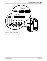
Location of the ventilation openings
Electrical Power
Before installing the melter, ensure that the melter will not be overloaded and
that the plant's electrical service is rated to handle the power required by the
melter and the hoses and applicators that you plan to use.
Refer to Appendix A,
Calculating Melter Power Requirements
,
for information
about how to calculate the maximum allowable hose lengths and applicator
wattages that can be used in your manufacturing application.
WARNING!
Risk of electrocution! Install a lockable power disconnect switch
between the electrical service and the melter. Failure to install or properly
use the disconnect switch when servicing the melter can result in personal
injury, including death.
Содержание AltaBlue
Страница 8: ...Table of Contents vi Part 1120130 E 2011 Nordson Corporation...
Страница 9: ...1 Setting Up Inputs Outputs 3 18 Setting Up Gear to Line Operation 3 23...
Страница 22: ...TABSHEET Introduction...
Страница 30: ...Introduction 2 8 Part 1120130 E 2011 Nordson Corporation...
Страница 31: ...TABSHEET Installation...
Страница 40: ...Hardware Installation and Setup 3 9 Part 1120130 E 2011 Nordson Corporation This page intentionally left blank...
Страница 58: ...TABSHEET Touchscreen...
Страница 69: ...TABSHEET Operation...
Страница 78: ...TABSHEET Configuration...
Страница 86: ...Configuring and Modifying Temperature Pump and Melter Settings 6 8 Part 1120130 E 2011 Nordson Corporation...
Страница 87: ...TABSHEET...
Страница 111: ...Service 7 24 Part 1120130 E 2011 Nordson Corporation Filter cartridge...
Страница 112: ...TABSHEET Troubleshooting...
Страница 129: ...TABSHEET Parts...
Страница 134: ...Parts 9 5 Part 1120130 E 2011 Nordson Corporation X Figure 9 1 One two pump melter frame assembly parts...
Страница 136: ...Parts 9 7 Part 1120130 E 2011 Nordson Corporation Figure 9 2 Three four pump melter frame assembly parts...
Страница 168: ...Parts 9 39 Part 1120130 E 2011 Nordson Corporation Figure 9 21 Manual pneumatic pressure control valve parts...
Страница 170: ...Parts 9 41 Part 1120130 E 2011 Nordson Corporation Figure 9 22 Flow control bypass control valve parts...
Страница 178: ...Parts 9 49 Part 1120130 E 2011 Nordson Corporation Schematics Figure 9 29 Flow control bypass control valve schematic...
Страница 182: ...Parts 9 53 Part 1120130 E 2011 Nordson Corporation Figure 9 32 Left panel assembly parts 400V melter shown...
Страница 186: ...Parts 9 57 Part 1120130 E 2011 Nordson Corporation Figure 9 34 One two pump melter 2 Hose Gun 400V back panel parts 50L...
Страница 188: ...Parts 9 59 Part 1120130 E 2011 Nordson Corporation This page intentionally left blank...
Страница 198: ...Parts 9 69 Part 1120130 E 2011 Nordson Corporation Figure 9 40 Two Hose Gun 400V melter right panel parts...
Страница 200: ...Parts 9 71 Part 1120130 E 2011 Nordson Corporation Figure 9 41 Four Hose Gun 400V melter right panel parts...
Страница 202: ...Parts 9 73 Part 1120130 E 2011 Nordson Corporation Figure 9 42 Six Hose Gun 400V melter right panel parts...
Страница 204: ...Parts 9 75 Part 1120130 E 2011 Nordson Corporation Figure 9 43 Eight Hose Gun 400V melter right panel parts...
Страница 208: ...Parts 9 79 Part 1120130 E 2011 Nordson Corporation This page intentionally left blank...
Страница 214: ...Parts 9 85 Part 1120130 E 2011 Nordson Corporation This page intentionally left blank...
Страница 219: ...Parts 9 90 Part 1120130 E 2011 Nordson Corporation...
Страница 220: ...TABSHEET...
Страница 225: ...TABSHEET Appendix A...
Страница 230: ......
Страница 231: ......
Страница 233: ...Index i Part 123456X E 2005 Nordson Corporation Index...
Страница 234: ...Index ii Part 123456X E 2005 Nordson Corporation...


