Hardware Installation and Setup
3-20
Part 1120130
E
2011
Nordson Corporation
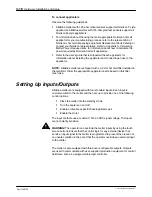
To wire inputs/outputs to the melter
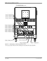
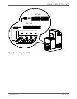
See Figure 3‐14.
1.
A female quick connector (32 pos PE) is located on the melter
right panel. Route a signal cable from the control equipment to the melter
through a male quick connector (32 pos PE). The male quick
connector has a PG-21 strain relief to fasten the signal cable. I/O
connector designation: -17X21 Function: transmits the digital
input/output signals and key-to-line signal between the parent machine
and the Nordson melter.
NOTE:
Use a signal cable suitable for NEC class1 remote control and
signaling circuits. To reduce the possibility of electrical shorting, route the
cable so that it does not touch nearby circuit boards.
2.
Connect each pair of input and output wires to the appropriate terminals
on I/O connector. Refer to table below for the terminal numbers that
correspond to each input.
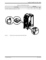
Figure
Location of the quick connector (-17X21) for connecting input/output wiring
Содержание AltaBlue
Страница 8: ...Table of Contents vi Part 1120130 E 2011 Nordson Corporation...
Страница 9: ...1 Setting Up Inputs Outputs 3 18 Setting Up Gear to Line Operation 3 23...
Страница 22: ...TABSHEET Introduction...
Страница 30: ...Introduction 2 8 Part 1120130 E 2011 Nordson Corporation...
Страница 31: ...TABSHEET Installation...
Страница 40: ...Hardware Installation and Setup 3 9 Part 1120130 E 2011 Nordson Corporation This page intentionally left blank...
Страница 58: ...TABSHEET Touchscreen...
Страница 69: ...TABSHEET Operation...
Страница 78: ...TABSHEET Configuration...
Страница 86: ...Configuring and Modifying Temperature Pump and Melter Settings 6 8 Part 1120130 E 2011 Nordson Corporation...
Страница 87: ...TABSHEET...
Страница 111: ...Service 7 24 Part 1120130 E 2011 Nordson Corporation Filter cartridge...
Страница 112: ...TABSHEET Troubleshooting...
Страница 129: ...TABSHEET Parts...
Страница 134: ...Parts 9 5 Part 1120130 E 2011 Nordson Corporation X Figure 9 1 One two pump melter frame assembly parts...
Страница 136: ...Parts 9 7 Part 1120130 E 2011 Nordson Corporation Figure 9 2 Three four pump melter frame assembly parts...
Страница 168: ...Parts 9 39 Part 1120130 E 2011 Nordson Corporation Figure 9 21 Manual pneumatic pressure control valve parts...
Страница 170: ...Parts 9 41 Part 1120130 E 2011 Nordson Corporation Figure 9 22 Flow control bypass control valve parts...
Страница 178: ...Parts 9 49 Part 1120130 E 2011 Nordson Corporation Schematics Figure 9 29 Flow control bypass control valve schematic...
Страница 182: ...Parts 9 53 Part 1120130 E 2011 Nordson Corporation Figure 9 32 Left panel assembly parts 400V melter shown...
Страница 186: ...Parts 9 57 Part 1120130 E 2011 Nordson Corporation Figure 9 34 One two pump melter 2 Hose Gun 400V back panel parts 50L...
Страница 188: ...Parts 9 59 Part 1120130 E 2011 Nordson Corporation This page intentionally left blank...
Страница 198: ...Parts 9 69 Part 1120130 E 2011 Nordson Corporation Figure 9 40 Two Hose Gun 400V melter right panel parts...
Страница 200: ...Parts 9 71 Part 1120130 E 2011 Nordson Corporation Figure 9 41 Four Hose Gun 400V melter right panel parts...
Страница 202: ...Parts 9 73 Part 1120130 E 2011 Nordson Corporation Figure 9 42 Six Hose Gun 400V melter right panel parts...
Страница 204: ...Parts 9 75 Part 1120130 E 2011 Nordson Corporation Figure 9 43 Eight Hose Gun 400V melter right panel parts...
Страница 208: ...Parts 9 79 Part 1120130 E 2011 Nordson Corporation This page intentionally left blank...
Страница 214: ...Parts 9 85 Part 1120130 E 2011 Nordson Corporation This page intentionally left blank...
Страница 219: ...Parts 9 90 Part 1120130 E 2011 Nordson Corporation...
Страница 220: ...TABSHEET...
Страница 225: ...TABSHEET Appendix A...
Страница 230: ......
Страница 231: ......
Страница 233: ...Index i Part 123456X E 2005 Nordson Corporation Index...
Страница 234: ...Index ii Part 123456X E 2005 Nordson Corporation...


