background image

Parts

9-54

Part 1120130

E


2011


Nordson Corporation

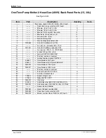
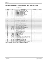
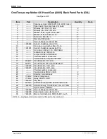
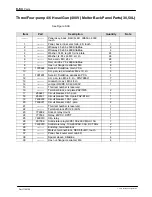
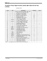
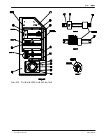
One/Two‐Pump Melter 2 Hose/Gun (400V) Back Panel Parts (15, 30L) 

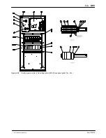
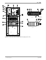
See Figure 9‐33.

Item

Part

Description

Quantity

Note

­­­­­­­­

­­­­­­­­

Panel assy, back, 2H/G, 2D, 15/30L, 400V, touch

1

­­­­­­­­

S

Panel, back, inner, elect cab, 2D, touch

1

2

­­­­­­­­

S

Wireway, 50 x 50 x 570, Alta

2

3

­­­­­­­­

S

Wireway, 25 x 50 x 300, Alta

3

4

­­­­­­­­

S

Washer, flt, M, reg, M3, zinc plate

17

5

­­­­­­­­

S

Washer, lk, M, spt, M3, stl, zn

17

6

­­­­­­­­

S

Nut, acorn, M3, stl, zn

17

7

­­­­­­­­

S

Rail, din, 300 lg, Alta

2

8

­­­­­­­­

S

Hex nut, flanged, serrated, M5

4

9

1078624

S

Svce kit, DuraBlue, main, PCA

1

10

­­­­­­­­

S

Scr, pan, rec, w/washer, M4 x 10, zn

4

11

1031201

S

Svce kit, DuraBlue, expansion PCA

1

12

­­­­­­­­

S

Scr, pan, rec, M3 x 8, zn ­ DIN 7985H

7

13

­­­­­­­­

S

Lockwshr M, ext, M3, stl, zn

7

14

­­­­­­­­

S

Jumper 3/N/PE, AC 400­230V

1

15

­­­­­­­­

S

This item number is reserved

16

­­­­­­­­

S

terminal block,end plate ZAP/TW3

1

17

256227

S

Circuit breaker, 2A 1­pole

1

18

256141

S

Circuit breaker 16A 3­pole FAZ­B16/3

1

19

7400072

S

Circuit breaker, 13A 1­pole

2

20

7400071

S

Circuit breaker, 32A 1­pole

1

21

­­­­­­­­

S

This item number is reserved

22

­­­­­­­­

S

Terminal block ZDU 2,5/4AN

2

23

­­­­­­­­

S

End stop, terminal block

6

24

779392

S

Socket, relay mount

1

25

777604

S

Relay, 24VDC, DPDT

1

26

7400010

S

Clip, relay

1

27

207396

S

Solid­state relay G3PE 100­260V MAX. 15A

2

28

7400070

S

Solid state relay, 100­260VAC, 35A, DC TRIG

1

32

­­­­­­­­

S

Spacer sleeve, AltaBlue

4

33

7403060

S

Hexnut, flanged, serrated, M6

4

34

7402290

S

Panel, back, outer, elect cab, 2D

1

35

7403476

S

Marker, terminal block, DEK 5/5+MC, touch

1

Содержание AltaBlue

Страница 1: ...t Manual Part 1120130A03 Issued 3 12 NORDSON CORPORATION DULUTH GEORGIA USA www nordson com This document contains important safety information Be sure to read and follow all safety information in thi...

Страница 2: ...ProLink Pro Meter Pro Stream RBX Rhino Saturn Saturn with rings Scoreguard Seal Sentry Select Charge Select Coat Select Cure Signature Slautterback Smart Coat Solder Plus Spectrum Speed Coat SureBead...

Страница 3: ...Tags 1 11 Introduction 2 1 Intended Use 2 1 Electromagnetic Compatibility EMC 2 1 Examples of Unintended Use 2 2 Residual Risks 2 2 Key Components 2 3 Electrical Components 2 4 Pump Shut Off Valve 2...

Страница 4: ...ors Indicate 4 4 About the Operator Display 4 5 State and Status Indicators from the Operator Display 4 6 Zone and Pump State Color Indicators 4 6 Zone and Pump Status Color Indicators 4 6 Master Cont...

Страница 5: ...irculation Control Valve Service Kit 7 18 Cleaning the Tank 7 19 Draining Material from the Tank 7 19 Cleaning the Tank by Hand 7 19 Tightening the Fixing Screws 7 19 Main PCA Board 7 20 To replace th...

Страница 6: ...9 40 Manual Pneumatic Pressure Control Valve Cabinet 9 42 Flow Control Bypass Control Valve Cabinet 9 43 Manual Pneumatic Pressure Flow Control Bypass Control Valve Interface Parts 9 45 Flow Control B...

Страница 7: ...ation 9 83 Pneumatic Pressure Control Valve 9 83 Line Speed Signal Generator 9 84 Optional Fittings 9 84 Recommended Spare Parts 9 86 Technical Data 10 1 General Data 10 1 Temperatures 10 1 Electrical...

Страница 8: ...Table of Contents vi Part 1120130 E 2011 Nordson Corporation...

Страница 9: ...1 Setting Up Inputs Outputs 3 18 Setting Up Gear to Line Operation 3 23...

Страница 10: ...nt can result in personal injury including death or damage to equipment or property Safety Alert Symbols The following safety alert symbol and signal words are used throughout this document to alert t...

Страница 11: ...ng regulations Contact the authority having jurisdiction for information S Maintain safety information including the safety labels affixed to the equipment in readable condition Instructions Requireme...

Страница 12: ...nction S are physically capable of performing their job function and are not under the influence of any substance that degrades their mental capacity or physical capabilities Applicable Industry Safet...

Страница 13: ...equired installation configuration does not match the installation instructions contact your Nordson representative for assistance S Position the equipment for safe operation Observe the requirements...

Страница 14: ...OTE MSDSs for cleaning compounds that are sold by Nordson are available at www nordson com or by calling your Nordson representative S Confirm the correct operation of all safety devices before placin...

Страница 15: ...he equipment system 2 To prevent the equipment from being accidentally energized lock and tag the disconnect switch es or circuit breaker s that provide input electrical power to the equipment and opt...

Страница 16: ...on melter read and comply with the material s MSDS Ensure that the material s processing temperature and flashpoints will not be exceeded and that all requirements for safe handling ventilation first...

Страница 17: ...h or circuit breaker the equipment may still be connected to energized auxiliary devices De energize and electrically isolate all auxiliary devices before servicing the equipment Failure to properly i...

Страница 18: ...damage the equipment and cause premature reaction of the hot melt If you are unsure of the equipment s ability to process PUR contact your Nordson representative for assistance HM CA CAUTION Before u...

Страница 19: ...pensing handguns by their proper suspension point First Aid If molten hot melt comes in contact with your skin 1 Do NOT attempt to remove the molten hot melt from your skin 2 Immediately soak the affe...

Страница 20: ...es the location of the product safety labels and tags affixed to the equipment Table 1 2 provides an illustration of the hazard identification symbols that appear on each safety label and tag the mean...

Страница 21: ...ags Item Part Description 1 1025795 WARNING Hazardous voltage Disconnect all power supply connections before servicing 2 224906 WARNING TAG WARNING ELEC SHOCK 3 224905 WARNING HOT 4 1100254 CAUTION HO...

Страница 22: ...TABSHEET Introduction...

Страница 23: ...able for personal injury or property damage resulting from unintended use Intended use includes the observance of Nordson safety instructions Nordson recommends obtaining detailed information on the m...

Страница 24: ...corrosive materials S Food products Residual Risks In the design of the unit every measure was taken to protect personnel from potential danger However some residual risks can not be avoided S Risk of...

Страница 25: ...2 1 provides the name and the location of key melter components Figure 2 1 Key melter components 1 Touch Screen 2 Protective panel removable 3 Tank lid 4 Main power switch 5 Motors 6 Filter cartridge...

Страница 26: ...ical components 1 Main board 2 Circuit breakers 3 RC suppressor 4 Fan 5 Pump controller 6 Signal conditioner 7 Expansion board 8 Power module 9 Main switch 10 Distribution block 11 Contactor 12 Lockou...

Страница 27: ...e The pump shut off valve allows replacement of the pump without first emptying the tank Figure 2 3 Location of the pump shut off valve Pressure Control Valves The manual pressure control valves can b...

Страница 28: ...xternal zones hoses standard and large applicators and air heaters confirming all zones are within their pre defined setpoint temperature range Standby All internal and external zones are reduced by t...

Страница 29: ...ed the model and part number of your melter when requesting service or ordering spare parts and optional equipment The model and part number are indicated on the equipment identification plate that is...

Страница 30: ...Introduction 2 8 Part 1120130 E 2011 Nordson Corporation...

Страница 31: ...TABSHEET Installation...

Страница 32: ...ents that must be assembled onto the melter by the customer Some additional materials must also be supplied by the customer to complete the installation If optional equipment was ordered with the melt...

Страница 33: ...r or timer 9 Flush the melter Experience of Installation Personnel The instructions provided in this section are intended to be used by personnel who have experience in the following subjects S Hot me...

Страница 34: ...Hardware Installation and Setup 3 3 Part 1120130 E 2011 Nordson Corporation Figure 3 1 One two pump melter minimum installation clearances...

Страница 35: ...Hardware Installation and Setup 3 4 Part 1120130 E 2011 Nordson Corporation Clearances contd Figure 3 2 Three four pump melter minimum installation clearances...

Страница 36: ...Hardware Installation and Setup 3 5 Part 1120130 E 2011 Nordson Corporation Figure 3 3 100L melter minimum installation clearances...

Страница 37: ...t the melter will not be overloaded and that the plant s electrical service is rated to handle the power required by the melter and the hoses and applicators that you plan to use Refer to Appendix A C...

Страница 38: ...en the melter and each applicator is dictated by the power requirement of each hose Refer to Appendix A Calculating Melter Power Requirements for information about how to determine the maximum allowab...

Страница 39: ...the components shown in Figure 3 6 The installation kit also contains a package of safety label overlays that are printed in variety of languages If required by local regulations the appropriate langu...

Страница 40: ...Hardware Installation and Setup 3 9 Part 1120130 E 2011 Nordson Corporation This page intentionally left blank...

Страница 41: ...pulsating current or universal current 30 mA may be used Connecting the Electrical Service NOTE The melter must be installed securely permanent power supply connection WARNING Operate only at the oper...

Страница 42: ...11 Part 1120130 E 2011 Nordson Corporation Table 3 1 Electrical Service Wiring Line voltage Terminals 1 2 3 N PE 400 VAC 3 phase with neutral star WYE D D D D D Figure 3 7 Location of service wiring...

Страница 43: ...To do this remove the O ring fitting from the return hose port and install the hose connector fitting from the ship with kit The return hose port is located on the rear of the melter at the top of the...

Страница 44: ...Nordson Corporation Pump 1 Output port 5 Pump 1 Output port 4 Pump 1 Output port 3 Pump 1 Output port 2 Pump 1 Output port 1 Pump 1 Output port 6 Pump 1 Output port 7 Figure 3 9 Connecting hoses one t...

Страница 45: ...rdson Corporation To connect hoses contd Pump 2 Output port 3 Pump 1 Output port 1 Pump 1 Output port 2 Pump 1 Output port 3 Pump 2 Output port 2 Pump 2 Output port 1 Figure 3 10 Connecting hoses one...

Страница 46: ...t 1 Pump 2 Stream 2 Output port 2 Pump 2 Stream 1 Output port 1 Pump 2 Stream 1 Output port 2 Pump 1 Stream 1 Output port 2 Pump 1 Stream 1 Output port 1 Pump 1 Stream 2 Output port 2 Pump 1 Stream 2...

Страница 47: ...p 3 Output port 2 Pump 3 Output port 1 Pump 3 Output port 6 Pump 3 Output port 7 Pump 2 Output port 3 Pump 1 Output port 1 Pump 1 Output port 2 Pump 1 Output port 3 Pump 2 Output port 2 Pump 2 Output...

Страница 48: ...Hardware Installation and Setup 3 17 Part 1120130 E 2011 Nordson Corporation Figure 3 13 Connecting a hose cordset...

Страница 49: ...re shipped with a 0 2 mm hot melt filter installed in the manifold Order the appropriate applicator nozzle based on this filter mesh size Setting Up Inputs Outputs AltaBlue melters are equipped with f...

Страница 50: ...firmware to provide one of the following outputs S The melter is ready S The melter is ready and the motor is enabled S A fault has occurred S The hot melt level is low only if the optional level swi...

Страница 51: ...nnector designation 17X21 Function transmits the digital input output signals and key to line signal between the parent machine and the Nordson melter NOTE Use a signal cable suitable for NEC class1 r...

Страница 52: ...utputs Set up the parameter control option for each input and output that you connected to the melter Table 3 2 lists the available control options Refer to Setting Up the Melter earlier in this secti...

Страница 53: ...l turn on the motor when the remote control feature is enabled from the user interface 10 Pump 2 remote on off 17X21 19 17X21 20 Input activated with 18 30 VDC The input is not polarity sensitive Acti...

Страница 54: ...0 VDC analog input signal NOTE Nordson offers a 0 10 VDC line speed signal generator Refer to Optional Accessories in Section 7 Parts for the part number To use the gear to line capability connect a 0...

Страница 55: ...The relay contact between terminals 17X21 25 17X21 26 17X21 27 17X21 28 17X21 29 17X21 30 17X21 3 1 17X21 32 are normally open When the motor is running these contacts should close Programming Use the...

Страница 56: ...poration 1 2 3 4 5 6 7 8 Figure 3 15 Motor drive keypad located on each motor drive inside the electrical enclosure 1 Graphic display 2 Mode button 3 ESC button 4 RUN button 5 Navigation keys 6 ENTer...

Страница 57: ...pattern control or timer Refer to the product manual provided with the device for information about installing and operating the equipment Flushing the Melter Before using the melter for production it...

Страница 58: ...TABSHEET Touchscreen...

Страница 59: ...erface to setup operate and maintain this melter Starting the Melter for the First Time The Configuration Setup wizard starts when you start the melter for the first time When prompted enter the follo...

Страница 60: ...greater detail About the Main Display Use the Main Display as the central location where you can access the following displays View color coded zone and pump status Master On Off controls Enable disa...

Страница 61: ...mperature Indicator Master Pump on Indicator Figure 4 2 The Monitor Display NOTE Touch the Monitor Display to access the Operator Display Accessing the Monitor Display S From the Main Display touch S...

Страница 62: ...at each status color indicates From the Touch Green The melter is READY and operating normally Yellow S Heating Cooling All internal external zones are either in the process of heating to from their s...

Страница 63: ...pumps as well as access the system Master Controls Color Description Main Display Monitor Display Anywhere on the display Touch any zone to Enable Disable Modify its setpoint temperature Touch any Pum...

Страница 64: ...e Operator Display The following tables detail what the state and status colors indicate for zones pumps and the master controls Zone and Pump State Color Indicators Color State Green Enabled White Di...

Страница 65: ...g table describes what each master control state color indicates Color State Dark Blue On White Off Light Blue Auto pump on Gray Not available About the Settings Display Use the Settings Display to co...

Страница 66: ...8 Part 1120130 E 2011 Nordson Corporation Touch To Configure Modify Temperature S Setpoints S Temperature limits S Standby settings S PID settings S Heater zone control S Ready delay Pump S Pump spee...

Страница 67: ...ace 4 9 Part 1120130 E 2011 Nordson Corporation About the System Primary Display Use the System Display to configure and modify system and melter settings Accessing the System Display S From the Main...

Страница 68: ...me format S Temperature format Firmware Version View the current software version number NOTE This is for viewing purposes only Password S Create Modify a Password S Enable Disable Password Protection...

Страница 69: ...TABSHEET Operation...

Страница 70: ...es S Operating pumps S Operating the master controls Starting the Melter Turn the main power switch to the On position The Main Display appears Initially the Monitor Display indicates an overall statu...

Страница 71: ...e the lid CAUTION Before filling the reservoir make sure both the hopper and the hot melt material are clean and free of foreign substances CAUTION Do not operate the melter on an empty or near empty...

Страница 72: ...parate zones when modifying either setpoint the system allows you to modify both setpoints together NOTE The Hopper setpoint temperature cannot exceed that of the reservoir TIP To minimize charring th...

Страница 73: ...a pump You can do one of the following S Enable or Disable the pump S Adjust its RPM S Change its Operation Mode X NOTE You can configure any available pump regardless of its state Enabled or Disable...

Страница 74: ...on Adjusting Pump RPM in Manual Mode 1 Access the Operator Display 2 Touch the pump that is configured for Manual operation 3 Touch Pump Speed RPM S Enter the RPM speed you want to use When done touch...

Страница 75: ...ess the Operator Display 2 Touch the pump that is configured for Gear to line operation 3 Touch Pump Speed RPM S Enter the Desired Pump Speed RPM you want to use 4 Touch Done Using the Master Controls...

Страница 76: ...what each Master Control color state indicates Color State Dark Blue On White Off Light Blue Auto On Master Pump only Gray Not available NOTE Auto On is a special state reserved only for the Master P...

Страница 77: ...or located on the front customer SD card Reverting back to Factory Settings You can reset all user definable system temperature and pump settings back to factory settings S From the Main Menu touch Sy...

Страница 78: ...TABSHEET Configuration...

Страница 79: ...Allow only qualified personnel to perform the following tasks Follow the safety instructions in this document and all other related documentation Overview The melter is shipped from the factory with m...

Страница 80: ...2011 Nordson Corporation Temperature Setpoint Temperature Temperature Limits Standby Settings PID Settings Heater Zone Control Ready Delay Global Individual Zones External Zones Internal Zones Pump P...

Страница 81: ...to alert you before an over under temperature fault occurs NOTE For setpoint limits the system uses the differential temperature conversion method For Celsius to Fahrenheit multiply Celsius by 1 8 For...

Страница 82: ...ine capability S Use manual to S Clean or purge the pump S Deliver adhesive output at a continuous rate Manual Manual Gear to Line Auto Pump Make better use of your time by allowing you to touch the M...

Страница 83: ...mp and Melter Settings 6 5 Part 1120130 E 2011 Nordson Corporation Managing System Settings The following table details what System settings you can configure and modify The following provides a quick...

Страница 84: ...on Corporation nput Output Formats Units Firmware Version Password Date Time Temperature Create Modify Timeout Enable Disable Display Brightness Contrast Screen Saver Delay Calibrate Screen Wipe Displ...

Страница 85: ...d contrast levels for easy viewing Brightness 75 Contrast 75 Brightness 30 60 75 100 Contrast 30 50 75 100 Screen Saver Delay Extend the usefulness of the display 5 minutes Min 1 minute Max 59 minutes...

Страница 86: ...Configuring and Modifying Temperature Pump and Melter Settings 6 8 Part 1120130 E 2011 Nordson Corporation...

Страница 87: ...TABSHEET...

Страница 88: ...ing System Pressure WARNING System and material pressurized Relieve system of pressure before disconnecting hoses applicators and hot melt handapplicators Failure to observe can result in serious burn...

Страница 89: ...on 2 Place a container under the drain valve ports located on the bottom of the manifold 3 Open all the drain valves Adhesive will drain from the valves 4 When adhesive stops draining close the drain...

Страница 90: ...iced Air hoses Inspect for damage Every time the melter is serviced Pump Tighten the gland bolt if present After initial startup Pump Check for leakage tighten gland bolt if present if necessary Depen...

Страница 91: ...lock out the motor drives but leave the main power on place the motion switch in the OFF position The main power to the melter will remain on and the melter will stay at application temperature Extern...

Страница 92: ...he new material S May not be mixed Thoroughly purge the unit with a cleaning agent recommended by the material supplier NOTE Properly dispose of the old material according to local regulations Detachi...

Страница 93: ...ld lubricant according to local regulations CAUTION Never mix different types of lubricants Lubricant Changing Interval Operating temperature 100 _C 212 _F Every 15 000 hours of operation or at least...

Страница 94: ...c side covers and the left and right control cabinet side covers Refer to Detaching the Exterior Panels earlier in this section as needed 3 Disconnect the motor cable wires noting their terminal posit...

Страница 95: ...g the motor coupling hub and sleeve toward the pump until the coupling sleeve engages with pump coupling hub 9 Ensure that the coupling sleeve cannot move then slide the motor assembly back 4 mm 0 16...

Страница 96: ...1 Ensure that the melter is turned off and that power has been disconnected and locked out 2 Ensure that the melter tank manifold and pump are cold 3 See Figure 7 4 Tighten the screws to 25 NSm 222 i...

Страница 97: ...tervals When leakage occurs tighten the pump gland bolt 1 Heat the pump to application temperature using a heated air blower 2 See Figure 7 5 Using a 24 mm short handle open end wrench with a 15 degre...

Страница 98: ...ain pan S cleaning supplies S replacement pump S replacement pump O rings S O ring lubricant S anti seize lubricant NOTE To rebuild a pump contact your Nordson representative for assistance 1 Ensure t...

Страница 99: ...Place a drain pan under the pump 6 See Figure 7 7 Loosen the screws that secure the motor to the base of the melter and then slide the motor back 7 Slide the coupling sleeve 2 off of the coupling hubs...

Страница 100: ...the manifold where the pump mates to it 10 Allow the melter to cool to room temperature 11 Install the pump coupling hub on the pump shaft ensure that it is flush with the pump shaft and tighten the...

Страница 101: ...e coupling sleeve cannot move then slide the motor assembly back 4 mm 0 16 in as indicated in Figure 7 9 4 mm 0 16 in Figure 7 9 Moving the motor assembly back 4 mm 0 16 in 16 Tighten the screws that...

Страница 102: ...essure Refer to Section 1 Safety M10 SW 24 3 Apply high temperature grease to all threads and O rings 4 Insert the filter cartridge and tighten it to approximately 15 NSm 133 in lb 5 Feed material by...

Страница 103: ...d high temperature grease Service Kit for P N refer to Section 7 Parts Required tools Open jawed wrench size 24 and size 13 3 2 2 2 Size 13 1 Size 24 1 Disassemble the hot filter cartridge material mu...

Страница 104: ...e of the insertion depth of the set screw dimension X This way the insertion depth can be replicated after reassembly 4 To prevent adhesive from leaking into the valve bore drain the tank Refer to Dra...

Страница 105: ...lter pressure 3 Measure insertion depth Refer to Pressure Control Valve 4 Use an open jawed wrench to screw out the pressure control valve then extract with a pliers 5 Remove old O rings and disassemb...

Страница 106: ...t heat tank to material softening temperature usually approximately 70 C 158 F NOTE The inside of the tank is release coated Do not use metallic tools to clean Do not use wire brushes This could damag...

Страница 107: ...5 Remove the four fastening screws that hold the board on the mounting studs and then remove the board NOTE Before installing the new board you must ensure that the board is properly configured for t...

Страница 108: ...111 R123 U26 C51 L2 U4 C12 RN5 R89 XP6 C31 RN6 RN4 DS13 R104 R54 R48 DS8 DS12 R35 R60 R64 DS10 DS11 R116 R94 Q16 R40 R41 C39 U23 D5 R2 R43 R46 C2 R128 R1 C40 R75 R119 R120 C37 C18 RN1 C15 RN11 C17 R95...

Страница 109: ...ers removed from the old board between terminals 1 and 2 d Install the second jumper between terminals 5 and 6 Figure 7 13 shows the jumpers installed Figure 7 13 100 ohm platinum melter jumpers insta...

Страница 110: ...ice 7 23 Part 1120130 E 2011 Nordson Corporation Maintenance Record Form Melter part Date Name Date Name Date Name Pump Motor gear box Fixing screws on pump and tank Air filter Tank Pressure control v...

Страница 111: ...Service 7 24 Part 1120130 E 2011 Nordson Corporation Filter cartridge...

Страница 112: ...TABSHEET Troubleshooting...

Страница 113: ...energized unit components active parts Failure to observe may result in an electric shock Safety S Never disconnect cables from or reconnect cables to the main board while the melter is energized S B...

Страница 114: ...the melter to its factory setting many common melter problems can be isolated to either a problem with the melter settings or the melter hardware 1 From the Main Display touch System Administration S...

Страница 115: ...ut of its slot 4 Using a computer that has a customer SD Card reader and is connected to the Internet you can now send the file to technical support 5 When done replace the customer SD Card back into...

Страница 116: ...d Alert condition an issue has been detected The melter continues to operate normally Fault condition if the issue is not resolved within 2 minutes of the alert message the master pump and heaters are...

Страница 117: ...s servicing Fieldbus card failure Replace the Fieldbus card Eight Hose applicator Board Failure Communication failure between main board and hose applicator board Replace hose applicator board Failed...

Страница 118: ...t setpoint to zero to avoid fault Replace main board or ribbon cable or CPU Expansion Board Connection Failure Communication failure between expansion board and main board Check the ribbon cable conne...

Страница 119: ...tor drive faults cause the pump to stop Refer to Table 8 4 for the motor drive fault codes To clear a motor drive fault correct the problem that caused the fault and then remove power from the motor d...

Страница 120: ...Corrective Action CrF Capacitor load circuit Motor drive hardware failure Replace the motor drive EEF EEPROM fault Internal memory fault S Check the environment electromagnetic compatibility S Replace...

Страница 121: ...rical enclosure fan is operating properly OLF Motor overload S Material exceeds the operating viscosity range S Excessive motor current S Overpressure condition caused by pressure control valve failur...

Страница 122: ...Corporation Motor Drive Faults contd 1 2 3 4 5 6 7 8 Figure 8 2 Changing a motor drive parameter 1 Graphic display 2 Mode button 3 ESC button 4 RUN button 5 Navigation keys 6 ENTer button 7 STOP butto...

Страница 123: ...andard Motor Frequency 50 drC Uns Nominal Motor Voltage on Name Plate 230 drC FrS Nominal Motor Frequency on Name Plate 102 drC nCr Nominal Motor Current on Name Plate 2 7 drC nsP Nominal Motor Speed...

Страница 124: ...Main power switch defective Replace main power switch 4 Main circuit breaker activated Switch on main circuit breaker 5 Main circuit breaker activated again Check for short circuit in melter or access...

Страница 125: ...d Exit or wait until standby period has expired 6 Motor overheated Ambient temperature too high Decrease ambient temperature by cooling or airing out Fan cap dirty Clean Pump blocked by foreign matter...

Страница 126: ...defective Replace pump 7 Pressure control valve setting too low Adjust pressure control valve Too Little Material Possible Cause Possible Fault Troubleshooting Corrective Action 1 Material supply hol...

Страница 127: ...control valve defective Replace 3 Pressure control valve set incorrectly Set to default Material Pressure Too Low Possible Cause Possible Fault Troubleshooting Corrective Action 1 Pump is worn Replac...

Страница 128: ...roubleshooting Corrective Action 1 Tank setpoint temperature set too high too low Correct temperature setting Others Problem Possible Cause Corrective Action 1 Leakage at pump shaft seal Pump shaft se...

Страница 129: ...TABSHEET Parts...

Страница 130: ...hown in the illustration A series of dashes in the parts column means the part cannot be ordered separately Description Provides the part name as well as its dimensions and other characteristics when...

Страница 131: ...VAC Wye 380 415 VAC Wye electrical service 8 11 Pump selection A SN0030 1 4 kg hr Single stream gear pump B SN0046 2 2 kg hr C SN0062 2 9 kg hr D SN0093 4 5 kg hr E SN0186 8 9 kg hr F SN0371 17 8 kg...

Страница 132: ...he solenoids to switch the hydraulic system between pneumatic pressure control mode by manually adjustable air pressure regulators and the volumetric mode which means that no material circulates throu...

Страница 133: ...Quantity Note Module Common 15 30L 2D AT 901 S Panel Assembly Tank Side 15 AND 30 Liter 2 902 S Panel Assembly Motor Cover Side 2 903 S Panel Assembly Motor Cover Front 1 904 S Panel Assembly Electri...

Страница 134: ...Parts 9 5 Part 1120130 E 2011 Nordson Corporation X Figure 9 1 One two pump melter frame assembly parts...

Страница 135: ...Liter 2 902 S Panel Assembly Motor Cover Side 2 903 S Panel Assembly Motor Cover Front 4D 1 904 S Panel Assembly Electrical Cover Front 4D 1 906 S Rivet Pop 1 8X 187 BLK ALUM 8 907 S Plug Button M32...

Страница 136: ...Parts 9 7 Part 1120130 E 2011 Nordson Corporation Figure 9 2 Three four pump melter frame assembly parts...

Страница 137: ...400294 S Castor swivel with lock 100 mm 130 kg 2 113 256800 S O ring 26 x 2 2 114 7400132 S O ring Viton 45 x 2 2 115 S Reservoir machined 1 116 S Screw socket M8 x 90 6 117 S Spring washer 16 mm OD 6...

Страница 138: ...Parts 9 9 Part 1120130 E 2011 Nordson Corporation Figure 9 3 One two pump melter reservoir manifold assembly parts 30L 2 SS assembly shown...

Страница 139: ...S Reservoir machined 1 116 S Screw socket M8 x 100 12 117 S Spring washer 16 mm OD 12 119 7400297 S Service kit heater 240V 800W 1 2 X 13 75 all melter manifolds 6 120 7400874 S Service kit heater 24...

Страница 140: ...Parts 9 11 Part 1120130 E 2011 Nordson Corporation Figure 9 4 Three four pump melter reservoir manifold assembly parts 30 50L 2SS 2SS assembly shown...

Страница 141: ...or 4 3 S Plate Drain 2DS 1 S Plate Drain 1SS 1 S Plate Drain 2SS 1 4 S SCR SKT M6X25 BL 10 5 S Washer LK M SPT M6 STL ZN 10 6 S Washer FLT M Narrow M6 STL ZN 10 7 973480 S Plug O ring STD THD M14X1 5...

Страница 142: ...1120130 E 2011 Nordson Corporation 12 01 03 05 06 08 02 12 APPLY 0 5 0 7 Nm TORQUE 12 08 12 04 13 07 12 08 APPLY 35 40 Nm TORQUE APPLY 35 40 Nm TORQUE Figure 9 5 Manifold assembly parts one or two du...

Страница 143: ...08 04 13 07 12 06 APPLY 55 60 Nm TORQUE 08 05 03 12 11 09 12 01 09 12 02 12 10 12 APPLY 35 40 Nm TORQUE APPLY 0 5 0 7 nm TORQUE APPLY 35 40 Nm TORQUE APPLY 55 60 Nm TORQUE APPLY 35 40 Nm TORQUE APPLY...

Страница 144: ...12 11 09 12 12 09 09 12 02 12 10 04 APPLY 55 60 Nm TORQU APPLY 0 5 0 7 Nm TORQ APPLY 35 40 Nm TORQU APPLY 55 60 Nm TORQUE APPLY 35 40 Nm TORQU APPLY 35 40 Nm TORQUE APPLY 55 60 Nm TORQUE APPLY 55 60 N...

Страница 145: ...external M3 2 208 7401366 S Thermoswitch ALTABLUE 1 209 7400298 S Service Kit Heater 240V 800W 1 2 X 11 65 one two pump melter 30 50L hopper 4 or 8 7400876 S Service Kit Heater 240V 500W 1 2 X 6 38 t...

Страница 146: ...234 S Screw button socket M5 x 10 12 235 779664 S Handle lid 1 236 S Screw pan M5 x 16 2 237 900298 S Compound heat sink 5 oz tube 1 238 900413 S Sealant RTV red 2 8 oz tube 1 239 S Rivet pop 1 8 x 0...

Страница 147: ...d SEE DETAIL A 202 203 204 205 238 221 220 223 224 225 222 237 209 201 239 240 234 237 208 236 235 223 224 241 233 232 229 230 231 228 227 226 219 218 215 216 217 213 203 214 212 203 211 210 206 207 F...

Страница 148: ...Heater 240V 500W 1 2 X 6 38 30L hopper 9 210 S Washer flat oversize M6 22 OD 18 211 S Screw socket M6 x 10 18 212 S Frame tank paint 2 213 S Washer flat regular M6 18 214 S Nut hex M6 12 215 S Washer...

Страница 149: ...oz tube 1 239 S Rivet pop 1 8 x 0 187 2 240 224905 S Tag warning hot 1 241 S Nut hex jam M5 4 242 931074 S Tape insulation 200 243 S Insulation foil backed 600W x 1200 L x 25 mm 1 245 S Sleeving insul...

Страница 150: ...08 237 209 237 210 203 211 212 213 203 214 215 216 217 218 219 220 221 222 225 224 223 226 227 228 229 230 231 232 233 234 235 236 240 239 241 224 223 246 247 213 203 248 238 205 249 250 Figure 9 9 Th...

Страница 151: ...g 35 x 2 1 303 S Adapter assembly single stream with shutoff 1 A S Adapter assembly dual stream with shutoff 1 B 304 S Spring washer 16 mm OD 4 305 S Screw socket M8 x 110 4 306 S Gear pump single str...

Страница 152: ...TREAM PUMP THIS V IEW SHOW S THE DUAL STREAM PUMP 309 302 303 304 309 302 309 301 TIGHTEN SCREWS 20 TO 25 N M 306 307 308 305 308 304 303 309 301 306 307 308 305 308 TIGHTEN SCREWS 20 TO 25 N M THIS V...

Страница 153: ...otary 1 03 Plate stop 1 04 Screw socket M5 x 12 4 05 Washer flat narrow M5 4 06 Washer lock split M5 4 07 207932 Valve safety 1 A 08 973480 Plug O ring straight thread M14 x 1 5 4 09 900223 Lubricant...

Страница 154: ...t M5 x 12 4 05 S Washer flat narrow M5 4 06 S Washer lock split M5 4 07 207932 S Valve safety 2 A 08 973480 S Plug O ring straight thread M14 x 1 5 5 09 900223 S Lubricant O ring Parker 4 oz 1 10 9003...

Страница 155: ...29106 Gear pump SN0371 3 71 cc rev 1 254279 729107 Gear pump SN0773 7 73 cc rev 1 254231 7116829 Gear pump SN1710 17 10 cc rev 1 253992 7131840 Gear pump SH0773 hardened 7 73 cc rev 1 259600 7130225 G...

Страница 156: ...Seal 1 NS S Allen Head Cap Screw M5X16 DIN912 A2 70 3 NS S High Temp Grease GLS 595 N2 CAN 10G 1 NS 7146229 S In Assembly Tools 7136915 7136918 EN GE 1 A NS 7136915 Assembly Tool F Shaft Sealing D12...

Страница 157: ...16 Inside Seal 1 NS S Allen Head Cap Screw M6X20 DIN912 SST 4 NS S High Temp Grease GLS 595 N2 CAN 10G 1 7136918 Assembly Tool F Shaft Sealing D16 assembly tool service kit NS S Assembly Mandrel F Sha...

Страница 158: ...cc rev 1 203640 7104180 Gear pump DN0062 2 x 0 62 cc rev 1 403729 7116269 Gear pump DN0093 2 x 0 93 cc rev 1 291997 7104181 Gear pump DN0186 2 x 1 86 cc rev 1 406435 7116268 Gear pump DN0279 2 x 2 79...

Страница 159: ...rporation Safety Valve Parts See Figure 9 15 Item Part Description Quantity Note 207932 Valve safety 85 bar 1 394592 Service kit 1 1 S O ring 11 x 2 1 2 S O ring 9 x 2 1 S High temp Grease GLS 595 N2...

Страница 160: ...le 401 7104265 S Filter cartridge MW0 2 VB reinf compl 1 A 401 S Plug M56x1 5 L35 1 402 203059 S Pressure ctrl valve 5 90 bar VB DB 1 B 207300 S Pressure ctrl valve 5 90 bar VB DB pneum 1 C 1070961 S...

Страница 161: ...Parts 9 32 Part 1120130 E 2011 Nordson Corporation Control Valve Module Parts contd Figure 9 16 Pressure control module parts...

Страница 162: ...ty Note 7104265 Filter cartridge mesh Size 0 2 mm complete 1 394590 Service Kit Filter 0 2 mm 1 S Filter sleeve Mesh Size 0 2 complete 1 S S Filter sheath D40 1 S S Filter sleeve MS 0 2 L104 1 S S O r...

Страница 163: ...valve 1 2 S Piston valve supporting ring 1 3 S Set screw black 90 bar 1 4 S Compression spring 2 2 x 7 4 x 34 4 1 5 S O ring 6 x 2 1 6 S O ring 11 x 2 1 7 S O ring 9 x 2 1 8 S Supporting ring Da10 Di...

Страница 164: ...1 3 S Cylinder bypass pneu Da19 3 1 4 S Valve body bypass pneumatic 50bar 90 psi 1 5 S Piston bypass pneu Da19 3 1 6 S Piston bypass pneu Da19 3 1 7 S Seal 19 7 x 0 6 1 8 S O ring 11 x 2 1 9 S O ring...

Страница 165: ...Parts 9 36 Part 1120130 E 2011 Nordson Corporation Pneumatic Pressure Control Valve Parts contd 9 6 7 5 1 11 8 2 4 3 10 Figure 9 19 Pneumatic pressure control valve parts...

Страница 166: ...6 T piece 1 7 Nipple double 1 8 Bulkhead connection iG1 4 1 9 Street el G1 4 x RP1 4 1 10 279615 Bypass valve 1 11 Item no not used 12 Sign max 6 0 1 13 Item no not used 14 Air coupling male AG1 4 L3...

Страница 167: ...4 2XD6 2 5 S Fitting Plug D06 2 6 S Fitting Plug D04 2 8 S Multi Plug Connector 4 Fitting 1 9 S Tubing Polyurethane 0 6 10 S Tubing Polyurethane 0 14 11 S AIE Hose D4 0 d2 5 PU BLUE 0 8 12 S AIE Hose...

Страница 168: ...Parts 9 39 Part 1120130 E 2011 Nordson Corporation Figure 9 21 Manual pneumatic pressure control valve parts...

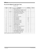
Страница 169: ...8 S Multi Plug Connector 4 Fitting 1 9 S Tubing Polyurethane 0 45 10 S Tubing Polyurethane 0 45 11 S Tubing Polyurethane 0 14 12 S AIE Hose D4 0 d2 5 PU BLUE 0 8 13 S AIE Hose D4 0 d2 5 PU BLUE 0 8 1...

Страница 170: ...Parts 9 41 Part 1120130 E 2011 Nordson Corporation Figure 9 22 Flow control bypass control valve parts...

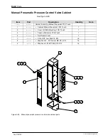
Страница 171: ...Manual Pneumatic PCV Touch 1 S Cabinet Manual Pneumatic FCB Touch 1 2 S Cover GUGUE Mounting FCB Touch 1 3 S Panel with Shutter FCB Touch 1 4 S Dust Guard Cover 1 7 S SCR SKT Low M4X10 ZN 16 8 S Wash...

Страница 172: ...matic FCB Touch 1 2 S Cover GUGUE Mounting FCB Touch 1 3 S Panel with Shutter FCB Touch 1 4 S Dust Guard Cover 1 5 S Heavy Connector Housing with Cover 1 6 S Heavy Connector Insert Female 16 PIN 1 7 S...

Страница 173: ...44 Part 1120130 E 2011 Nordson Corporation Flow Control Bypass Control Valve Cabinet contd 08 09 08 09 11 09 06 08 12 01 07 10 07 03 07 02 04 05 13 Figure 9 24 Flow control bypass control valve cabine...

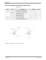
Страница 174: ...erated hose D8 0 d6 0 PU blue 2 3 S female air coupling d6 NW7 2 L60 1 4 S male air coupling KS4 1 4 A 1 5 S Sealing Ring R1 4 Type PDR 14 2 6 S Bulkhead Connection IG1 4 1 7 S Double Nipple AR1 4 AR1...

Страница 175: ...mbly 1 4 Unit FCB Touch 1 S Fixing Plate 2 3 Valve AOPCV FCB 1 2 7403314 S Service kit Solenoid Valve 2 3 1 Unit 1 S Solenoid Valve 2 3 2 Unit 1 S Solenoid Valve 2 3 3 Unit 1 S Solenoid Valve 2 3 4 Un...

Страница 176: ...27 Item Part Description Quantity Note Multi Plug Connector 1 Multi Plug Connector Socket 1 2 Multi Plug Connector Plug 1 3 BARB Fitting Socket 4 BARB Fitting Plug 5 SCR SKT Low M4X10 ZN 4 6 Washer FL...

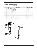
Страница 177: ...Body circulation valve 1 2 S Spool circulation valve 1 3 S Nut hex M12 1 4 S O ring 9 x 2 1 5 S O ring 11 x 2 1 6 S O ring Viton 0 239 ID x 0 070 W 1 7 S Screw set cup M4 x 4 stainless steel 1 394600...

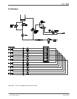
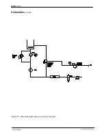
Страница 178: ...Parts 9 49 Part 1120130 E 2011 Nordson Corporation Schematics Figure 9 29 Flow control bypass control valve schematic...

Страница 179: ...Parts 9 50 Part 1120130 E 2011 Nordson Corporation Schematics contd Figure 9 30 Manual pneumatic pressure control valve schematic...

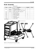
Страница 180: ...M24 DAN SN1710 SN1710 pumps only 1 502 7402295 S Service Kit Motor BG06 31 D06LA4TOF 1 503 S Plate mount motor 1 504 S Washer flat regular M8 8 505 S Washer lock split M8 8 506 S Screw socket M8 x 25...

Страница 181: ...8 5 S WireWay 25X65X180 ALTABLUE 1 6 S Stock WireWay 25X65 ALTABLUE 0 22 7 S Washer FLT M REG M3 Zinc Plate 10 8 S Washer LK M SPT M3 STL ZN 10 9 S Nut Acorn M3 STL ZN 10 10 S DIN Rail 280 LG 1 11 S H...

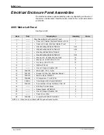
Страница 182: ...Parts 9 53 Part 1120130 E 2011 Nordson Corporation Figure 9 32 Left panel assembly parts 400V melter shown...

Страница 183: ...rec M3 x 8 zn DIN 7985H 7 13 S Lockwshr M ext M3 stl zn 7 14 S Jumper 3 N PE AC 400 230V 1 15 S This item number is reserved 16 S terminal block end plate ZAP TW3 1 17 256227 S Circuit breaker 2A 1 p...

Страница 184: ...Parts 9 55 Part 1120130 E 2011 Nordson Corporation Figure 9 33 One two pump melter 2 Hose Applicator 400V back panel parts 15L 30L...

Страница 185: ...ext M3 stl zn 7 14 S Jumper 3 N PE AC 400 230V 1 15 S This item number is reserved 16 S terminal block end plate ZAP TW3 1 17 256227 S Circuit breaker 2A 1 pole 1 18 256141 S Circuit breaker 16A 3 pol...

Страница 186: ...Parts 9 57 Part 1120130 E 2011 Nordson Corporation Figure 9 34 One two pump melter 2 Hose Gun 400V back panel parts 50L...

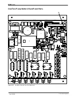
Страница 187: ...J2 R86 RV 10 R26 XP5 C58 R111 R123 U26 C51 L2 U4 C12 RN5 R89 XP6 C31 RN6 RN4 DS13 R104 R54 R48 DS8 DS12 R35 R60 R64 DS10 DS11 R116 R94 Q16 R40 R41 C39 U23 D5 R2 R43 R46 C2 R128 R1 C40 R75 R119 R120 C3...

Страница 188: ...Parts 9 59 Part 1120130 E 2011 Nordson Corporation This page intentionally left blank...

Страница 189: ...7 13 Lockwshr ext M3 stl zn 7 14 Jumper 3 N PE AC 400 230V 1 15 This item number is reserved 16 terminal block end plate ZAP TW3 1 17 256227 Circuit breaker 2A 1 pole 1 18 256141 Circuit breaker 16A 3...

Страница 190: ...Parts 9 61 Part 1120130 E 2011 Nordson Corporation Figure 9 36 One two pump melter 4 6 Hose Gun 400V back panel parts 15L 30L...

Страница 191: ...Lockwshrm ext M3 stl zn 7 14 Jumper 3 N PE AC 400 230V 1 15 This item number is reserved 16 Terminal block end plate ZAP TW3 1 17 256227 Circuit breaker 2A 1 pole 1 18 256141 Circuit breaker 16A 3 po...

Страница 192: ...Parts 9 63 Part 1120130 E 2011 Nordson Corporation Figure 9 37 One two pump melter 4 6 Hose Gun 400V back panel parts 50L...

Страница 193: ...raBlue expansion PCA 1 12 Scr pan rec M3 x 8 zn DIN 7985H 7 13 Lockwshrm ext M3 stl zn 7 14 Jumper 3 N PE AC 400 230V 1 15 This item number is reserved 16 Terminal block end plate ZAP TW3 2 17 256227...

Страница 194: ...Parts 9 65 Part 1120130 E 2011 Nordson Corporation Figure 9 38 Three four pump 4 6 Hose Gun 400V melter back panel parts 30 50L...

Страница 195: ...wshrm ext M3 stl zn 7 14 S Jumper 3 N PE AC 400 230V 1 A 15 S This item number is reserved 16 S Terminal block end plate ZAP TW3 2 17 256227 S Circuit breaker 2A 1 pole 1 18 256141 S Circuit breaker 1...

Страница 196: ...Parts 9 67 Part 1120130 E 2011 Nordson Corporation Figure 9 39 Three four pump 4 6 Hose Gun 400V melter back panel parts 30 50L...

Страница 197: ...langed serrated M5 10 15 S This item number is reserved 16 7401320 S Service kit fan 240VAC 170 CFM 1 17 7401321 S Service kit filter fan elect cab 1 18 S Screw shcs M4 X 45 GD 8 8 ZP 2 19 S Panel cov...

Страница 198: ...Parts 9 69 Part 1120130 E 2011 Nordson Corporation Figure 9 40 Two Hose Gun 400V melter right panel parts...

Страница 199: ...errated M5 10 15 S Board breakout DuraBlue expand tb 20POS 1 16 7401320 S Service kit fan 240VAC 170 CFM 1 17 7401321 S Service kit filter fan elect cab 1 18 S Screw shcs M4 X 45 GD 8 8 ZP 2 19 S Pane...

Страница 200: ...Parts 9 71 Part 1120130 E 2011 Nordson Corporation Figure 9 41 Four Hose Gun 400V melter right panel parts...

Страница 201: ...4 ch 1 12 S Scr pan rec M4x10 zn 4 13 S Washer lk M ext M4 stl zn 4 15 S Board breakout DuraBlue expand tb 20pos 1 16 7401320 S Service kit fan 240VAC 170 CFM 1 17 7401321 S Service kit filter fan el...

Страница 202: ...Parts 9 73 Part 1120130 E 2011 Nordson Corporation Figure 9 42 Six Hose Gun 400V melter right panel parts...

Страница 203: ...serrated M5 10 15 S Board breakout DuraBlue expand tb 20pos 2 16 7401320 S Service kit fan 240VAC 170 CFM 1 17 7401321 S Service kit filter fan elect cab 1 18 S Screw shcs M4 x 45 gd 8 8 zp 2 19 S Pan...

Страница 204: ...Parts 9 75 Part 1120130 E 2011 Nordson Corporation Figure 9 43 Eight Hose Gun 400V melter right panel parts...

Страница 205: ...Bottom Electrical Cabinet 2D Touch 1 2 S EMI Filter 500VAC 60A 3P N PE 1 3 S Terminal Block Ground Touch 1 4 S Grommet Rubber ID32 5 5 S SCR SKT M8X20 ZN 4 6 S Washer FLT M REG 8 STL ZN 4 7 S LockWas...

Страница 206: ...al Cabinet 4D 100L Touch 1 2 S EMI Filter 500VAC 60A 3P N PE 1 3 S Terminal Block Ground Touch 1 4 S Mount Saddle Tie DIA 6 2 5 S Grommet Rubber ID32 8 6 S SCR SKT M8X20 ZN 4 7 S Washer FLT M REG 8 ST...

Страница 207: ...Service Kit LCD MODULE 1 0004 7403315 S Service Kit PCA Motor Control Touch 1 0005 S THRDSPCRMM Male Female ss hex M3 8MMLG 6 0006 S Washer LK M INT M3 STL ZN 6 0007 S Clamp Ribbon Cable 1 0008 S SCR...

Страница 208: ...Parts 9 79 Part 1120130 E 2011 Nordson Corporation This page intentionally left blank...

Страница 209: ...512 Hose Connect Assembly PT 6H G 2D Touch 1 7403513 Hose Connect Assembly PT 2H G 100L Touch 1 7403514 Hose Connect Assembly PT 4H G 4D 100L Touch 1 7403515 Hose Connect Assembly PT 6H G 4D 100L Touc...

Страница 210: ...Parts 9 81 Part 1120130 E 2011 Nordson Corporation Figure 9 47 Sensor assembly parts four pump 100 ohm platinum melter shown...

Страница 211: ...01273 Low level indication 50L one two pump 7401274 Low level indication 30 50L three four pump 7401275 Low level indication 100L 1201 S Wire harness low level 1 1202 S Low level assembly 169 mm 1 NS...

Страница 212: ...Note 7400563 Low level indication 15 30L one two pump 7401273 Low level indication 50L one two pump 7401274 Low level indication 30 50L three four pump 7401275 Low level indication 100L NOTE Refer to...

Страница 213: ...ittings See Figure 9 49 These fittings can be used at the melter end of a hose Hose Size Fitting Part Number Fitting Type Fitting Size Melter Side Fitting Size Hose Side 8 mm 7400333 Straight M16 x 1...

Страница 214: ...Parts 9 85 Part 1120130 E 2011 Nordson Corporation This page intentionally left blank...

Страница 215: ...elter and 100L melter reservoirs 7401366 Thermoswitch Assembly ALTABLUE 777604 Relay 24VDC DPDT 779392 Socket Relay Mount 7401321 Service Kit Filter Fan Electrical Cabinet 7401320 Service Kit Fan 240V...

Страница 216: ...vice kit insulation reservoir 100L 7403281 Service kit insulation hopper 15L W R 2D 7403282 Service kit insulation hopper 30L W R 2D 7403283 Service kit insulation hopper 50L W R 2D 7403284 Service ki...

Страница 217: ...tream PUMP SIZE SN1710 7104645 Service Kit PUMP O ring DUAL STREAM Select Based on Specific Melter Configuration One Two Pump Melters 240 VAC 7400762 Main Contactor 600V 50hz 60hz 3 pole 80 A 7104855...

Страница 218: ...60 Circuit Breaker 25 A 3 pole inductive load Three Four Pump and 100L Melters 400 and 480 VAC 7400762 Main Contactor 600V 50hz 60hz 3 pole 80 A 7400483 Contactor 40 A 440V 3 phase 240 VAC coil 740038...

Страница 219: ...Parts 9 90 Part 1120130 E 2011 Nordson Corporation...

Страница 220: ...TABSHEET...

Страница 221: ...re 5 to 85 bar 0 5 to 8 5 MPa 72 5 to 1 233 psi Melting capacity 1 tank full per hour Degree of protection IP 33 Noise emission 70 dB Motor type 3 ph AC motor Gear box type Helical gear Motor pump spe...

Страница 222: ...30L 23166W 50L 25232W Three four pump melter Four hose applicator 30L 18684W 50L 20750W Six hose applicator 30L 20521W 50L 22587W Eight hose applicator 30L 24194W 50L 26161W Max load per hose receptac...

Страница 223: ...mp melter 1 2 single stream 1 2 dual stream 1 2 single stream 1 2 dual stream 1 2 single stream 1 2 dual stream Number of pumps one two pump melter Not applicable 2 single stream 2 dual stream 2 singl...

Страница 224: ...0130 E 2011 Nordson Corporation Hydraulic Schematic HOPPER GRID ADHESIVE TCS GEAR MOTOR CONTROL FILTER PUMP CV PRV GEAR FILTER PUMP CV PRV MOTOR CONTROL DRAIN VALVE DRAIN VALVE MOTOR MOTOR Figure 10 1...

Страница 225: ...TABSHEET Appendix A...

Страница 226: ...t is dispensed The following three maximum wattages must be considered when calculating melter power requirements S Single component maximum The wattage of any single hose or gun S Hose gun pair maxim...

Страница 227: ...O TAG Component Maximum Wattage A Any single hose or gun 1000W B Any hose gun pair 1200W C Sum of hose gun pairs 1 and 2 2000W Sum of hose gun pairs 5 and 6 2000W D Any single hose or gun 3 or 4 2000W...

Страница 228: ...4 motor 25021 3 N PE AC 400 230 V 50 60 Hz 43A 3 motor 25021 3 N PE AC 400 230 V 50 60 Hz 41A 2 motor 23992 3 N PE AC 400 230 V 50 60 Hz 39A 1 motor 23478 3 N PE AC 400 230 V 50 60 Hz 39A 15L 6 H G 2D...

Страница 229: ...50L Hopper 7402317 HEATER 240V 800W 50DIA X 11 65LG 8 61 72 Reservoir 7400481 HEATER CARTRIDGE 240V 400W 50DIA X 13 75LG 3 123 144 Manifold 7400051 HEATER CARTRIDGE 240V 800W 50DIA X 13 75 LG 3 61 72...

Страница 230: ......

Страница 231: ......

Страница 232: ...Product Manual 123456X Title Customer Product Manual 123456X Title Customer Product Manual 123456X Title Customer Product Manual 123456X Title Customer Product Manual 123456X Title Customer Product M...

Страница 233: ...Index i Part 123456X E 2005 Nordson Corporation Index...

Страница 234: ...Index ii Part 123456X E 2005 Nordson Corporation...

Отзывы: