21
is restored.
The temperature range is set from a minimum to a maximum
value. Refer to par. A.2.2 for details on temperatures.
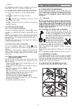
C.2.4 TEMPERATURE CONTROLLER SIGNALLING ICONS
The temperature controller has several signalling ICONS:
-
Icon
lit up indicates compressor activation.
-
Icon
indicates that a temperature alarm has occurred
during appliance operation.
-
Icon
indicates that a service alarm has occurred during
appliance operation.
C.2.5 SIGNALLING AND ALARMS
C.2.5.1 Service alarms and signalling
The alarm is signalled by lighting up of the
Icon
Alarm
signalling is also indicated by the alarm code appearing on the
display.
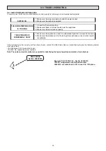
Example: Alarm signalling due to a faulty probe (compartment
probe) appears directly on the instrument display with the
message “E0” and “rE” flashing alternately (refer to position 1 of
the alarms table).
When the alarm condition ceases, the alarm goes off. Otherwise,
contact the After-Sales Service.
C.2.5.2 Temperature alarms and signalling
The alarm is signalled by lighting up of the
Icon
.
Alarm
signalling is also indicated by the alarm code appearing on the
display.
Temperature alarm signalling, regarding the thermostatting
probe, appears directly on the instrument display with the
indication “HI” (max. temperature alarm) and “LO” (min. tempe-
rature alarm).
C.2.6 DEFROST FOR FREEZER MODELS
(with evaporating grilles)
Manual defrosting must be carried out for these models when
the layer of frost is more than 5 mm thick. To defrost, carry out
these instructions:
- remove any load present in the compartment and put it in
another available freezer unit;
- position the water tray (supplied) on the bottom of the com-
partment;
- switch off the appliance with the
“ON/OFF”
button;
- unplug the appliance;
- open the door and wait until all the ice on the evaporating
grilles has melted and the water has run into the tray;
- empty the tray (several times if necessary);
- reconnect the power by plugging in the appliance;
- switch the appliance on with the
“ON/OFF”
switch;
- wait for the compartment temperature to reach that required
(according to the setting);
- put back the load previously removed.
D.1.1 PRECAUTIONS FOR MAINTENANCE
Routine maintenance operations can be carried out by non-
specialised personnel, carefully following the instructions given
below.
The manufacturer declines any liability for operations
carried out on the appliance without following these
instructions.
ATTENTION
:
Do not touch the appliance with wet hands and/or feet or
when barefoot. Before carrying out any cleaning or mainte-
nance operation, disconnect the appliance from the power
supply and carefully unplug it. DO NOT remove the safety
guards for routine maintenance operations. Use protection
equipment (protective gloves).
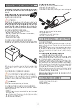
D.1.2 CLEANING THE CABINET AND ACCESSORIES
Clean the stainless steel parts every day with
lukewarm water and neutral soap or products that
are over 90% biodegradable (in order to reduce
the emission of pollutants into the environment),
then rinse and dry thoroughly. Do not use solvent-
based detergents (e.g. trichloro-
ethylene) or abrasive powders for
cleaning. Do not use spray products
for defrosting; in fact, they can be
harmful to the health and/or damage
the materials the appliance is made from. It is
advisable to go over the stainless steel surfaces
with a rag moistened with paraffin oil in order to create a
protective film.
Check the power cable regularly and replace it in case of signs
of wear.
Have the appliance checked periodically (at least once a year).
D.1.3 COMPARTMENT CLEANING
In refrigerated models the racks can be removed for thorough
compartment cleaning (remove them before starting cleaning);
to remove, just pull them out (proceed in reverse order to refit).
Clean the compartment with products that are over 90% biode-
gradable, then rinse and dry thoroughly.
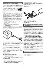
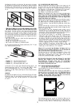
D.1.4 REPLACING THE THERMOMETER BATTERY
To replace the thermometer battery, proceed as follows:
1
2
b
NEW
NEW
c
a
d
D.1 ROUTINE MAINTENANCE


