55
EN
Link function
CAUTION
z
z
When the link function is used, the following functions cannot be used.
Output of channel switching signal
Forced stop signal
z
z
With one workpiece signal input, all linked electric screwdrivers operate.
It is not possible to assign individual workpiece signal input to each electric screwdriver.
z
z
Always connect an external power supply and reset switch.
z
z
For connection, use thick wire as much as possible. (AWG20 or more is recommended)
z
z
For connection of an external signal, use a commercially available terminal block.
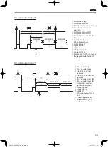
A function that links up to 10 electric screwdrivers is called the link function.
Because the screwdriver starts in order upon connection, you can understand which electric screwdriver is used
according to the screw tightening order, achieving a work system with less error.
1
2
3
0
Electric screwdrivers start in order of connection and when the set screw count is reached, the next connected electric
screwdriver becomes operable.
One electric screwdriver is operated at a time. Two or more screwdrivers cannot be operated at the same time.
1
Turn off the power of the connected electric screwdriver
2
Connect (wire) the I/O signal
Refer to the example of link connection and settings (p. 56) to connect an external power supply, switches and
sensors. To use the link function, an external power supply and reset switch are required.
3
Turn ON the power of the electric screwdriver
4
Press and hold the [MEMORY] button and [SELECT] button
The mode enters function setting mode.
5
Use the [SELECT] button, [UP] button, and [DOWN] button to set the following functions
Function
No.
Function
Setting
5
OK signal output timing
0: When the set count ends
13
Pin No. 7 output switching
1: LINK-OUT
14
Pin No. 4 input switching
1: LINK-IN
6
Press and hold the [MEMORY] button to save the setting
Make the same setting for all connected electric screwdrivers.
TV07521-1_DLV30S12P-AYK_en.indb 55
2017/02/10 15:56:38


