NIP
Pollux GigE Series – 01M / 05M Camera
Page
45
of
56 Manual 1.0
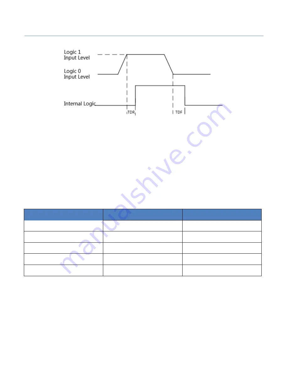
Figure 59.
Inputting Logic Level
Please connect to GND pin first to protect GPIO pin and then input voltage to Line2
pin.
②
Configure Line2 to output pin
The available maximum current is 25mA and the output impedance is 40Ω.
When the environment temperature is 25 degree centigrade, the relationship
among external voltage, impedance and the output low level can be shown in
Table 9.
External Voltage
External Resistor
VL (GPIO2)
3.3V
1KΩ
160mV
5V
1KΩ
220mV
12V
1KΩ
460mV
24V
1KΩ
860mV
30V
1KΩ
970mV
Table 9.
The Parameter of Output Logic Low Level
When the external voltage of 1KΩ external resistance turns to 5V, features of
output logic level and electric feature in GPIO2 configuration can be shown in
Figure 3-58 and Table 10.


