background image

24 - Electrical System

48

Service Manual – SC250, Scrubtec 334, MA 30

Troubleshooting

Trouble

Possible Causes

Remedy

The machine is not working

Battery (BAT) flat or connections faulty

Charge the battery or clean the 

connections

Battery (BAT) broken

Check the battery no-load voltage

The battery will not charge

The battery charger (CH) is broken

Replace

Note: 

Damage to the battery charger or its connections can prevent the machine from 

operating properly.

Battery LED behavior 

Scenario

Yellow 

LED

Red 

LED

Description

Consequence

Indication on the machine display 

battery LEDs

Charging in High 

temperature

ON

OFF

Indicates slow charge 

above +40°C

None, only slower charging 

than usual

No indication

Charging in Low 

temperature

ON

OFF

Indicates slow charge 

below +10°C

None, only slower charging 

than usual

No indication

Charge 

temperature too 

high

OFF

200mS 

On/Off

No charging above +50°C 

(Relevant Green LED On)

Stop charging

1 solid Green LED, indicating actual 

capacity.

Charge 

temperature too 

low

OFF

200mS 

On/Off

No charging below 0°C 

(Relevant Green LED On)

Stop charging

1 solid Green LED, indicating actual 

capacity.

Charge current 

too low

400mS 

On/Off

OFF

Indicates that charger 

is removed before fully 

charged

None

1 solid Green LED, indicating actual 

capacity. (10 sec.)

Charge current 

too high

400mS 

On/Off

400mS 

Off/On

Indicates that the charge 

current is too high

Stop charging

1 solid Green LED, indicating actual 

capacity.

Charge current 

overload

ON

200mS 

On/Off

Indicates a charge 

overcurrent (Inrush)

Stop charging

1 solid Green LED, indicating actual 

capacity. (10 sec.)

Discharge 

temperature too 

high

OFF

200mS 

On/Off

Indicates a discharge 

temperature above 55°C

Stop machine functions

1 solid Green LED, indicating actual 

capacity. (10 sec.)

Discharge 

temperature too 

low

OFF

200mS 

On/Off

Indicates a discharge 

temperature below -20°C

Stop machine functions

1 solid Green LED, indicating actual 

capacity. (10 sec.)

Discharge 

current too high

OFF

200mS 

On/Off

Indicates a discharge 

current above 25 Amp (5 

seconds)

Stop machine functions

1 solid Green LED, indicating actual 

capacity. (10 sec.)

Discharge 

overload

OFF

200mS 

On/Off

Indicates a discharge 

current above 30 Amp 

(400mS)

Stop machine functions

1 solid Green LED, indicating actual 

capacity. (10 sec.)

Battery capacity 

low warning

400mS 

On/Off

OFF

Indicates capacity below 

10% or cell below 3.2-V

None

1 flashing Green LED

Battery empty

400mS 

On/Off

OFF

Indicates empty battery 

pack

No machine functions

No indication

Mosfet 

temperature too 

high

400mS 

On/Off

400mS 

On/Off

Indicates that the Mosfets is 

too hot (>90%)

Stop machine functions

1 solid Green LED, indicating actual 

capacity. (10 sec.)

Battery pack 

defect

OFF

Special

Indicates that the battery 

pack should be replaced

Stop machine functions

1 solid Green LED, indicating actual 

capacity. (10 sec.)

Содержание Advance 9087381020

Страница 1: ...SC250 Scrubtec 334 MA 30 Service Manual Advance SC250 9087381020 Nilfisk SC250 9087380020 Nilfisk Scrubtec 334 9087382020 Clarke MA 30 9087383020 English 08 2016 Revised 03 2017 Form No 9100002116 ...

Страница 2: ...cations 19 Removal and Installation 20 Main Machine Controller EB1 20 Main Control Board EB2 and Hand Presence Sensors S1 S2 26 Specifications 30 Main Machine Controller EB1 Connectors 30 Main Control Board EB2 Connectors 35 10 Chassis System 38 Chassis main parts 38 14 Wheel System Non Traction 39 Functional Description 39 Component Locations 39 Specifications 40 24 Electrical System 41 Functiona...

Страница 3: ...justments 66 Brush and Brush Compartment Cleaning 66 Troubleshooting 67 Brush Motor Amperage Check 68 Removal and Installation 70 Driving Belt 70 Brush Motor 72 Specifications 75 38 Squeegee System 76 Functional Description 76 Maintenance and Adjustments 78 Squeegee Bar Cleaning 78 Troubleshooting 79 Removal and Installation 80 Vacuum Duct 80 Specifications 84 40 Recovery System 85 Functional Desc...

Страница 4: ... resource intended to help service technicians when carrying out mainte nance and repairs on the scrubber dryer to guarantee the best cleaning performance and a long working life for the machine Please read this manual carefully before performing any maintenance and repair procedure on the machine Other Reference Manuals Model Product Code User Manual Spare Parts List Nilfisk SC250 9087380020 9100...

Страница 5: ...erator s position that is to say in driving position Serial Number Label Reference to Figure 1 The machine serial number and model name are marked on the plate see the example to the side Product code and year of production are marked on the same plate Date code A16 means Janu ary 2016 This information is useful when requiring ma chine spare parts Figure 1 ...

Страница 6: ...structions before performing any operation on the machine 2 Warning Do not use the machine on slopes with a gradient exceeding the specifications Symbols Danger It indicates a dangerous situation with risk of death for the operator Warning It indicates a electrostatic sensitive components Warning It indicates a potential risk of injury for people or damage to objects Caution It indicates a caution...

Страница 7: ...modified batteries may exhibit unpredictable behavior resulting in fire explosion or risk of injury Do not expose a battery pack or appliance to fire or excessive temperature Exposure to fire or tempera ture above 130 C 256 F may cause explosion Do not store use or recharge in environments with a temperature higher than 45 C Do not recharge with temperatures lower than 0 C Due to the risk of short...

Страница 8: ...sembled it can cause damages to people and prop erties Take all necessary precautions to prevent hair jewels and loose clothes from being caught by the machine moving parts Do not use the machine on slopes Do not use the machine on slopes with a gradient exceeding the specifications Do not use the machine in particularly dusty areas Use the machine only where a proper lighting is provided While us...

Страница 9: ...r and safe operation the scheduled maintenance shown in the relevant chapter of this Manual must be performed by the authorised personnel or by an authorised Service Center Do not wash the machine with direct or pressurised water jets or with corrosive substances The machine must be disposed of properly because of the presence of toxic harmful materials batteries etc which are subject to standards...

Страница 10: ...nction block push button free handlebar inclination Battery charging symbol Function block push button front squeegee lifted Front squeegee lifting lever Knobs with operator palm sensors Handlebar inclination adjustment lever Start stop switch Solution switch Vacuum system push button Knobs with operator palm sensors ...

Страница 11: ...very tank cover Tanks solution and recovery water container Machine body cleaning deck Brush engagement dis engagement lever Brush floor pressure regulation knob Park pedal lifted for washing drying Park pedal pressed for parking movement Front wheels Tanks container lifting handle Handlebar with control panel ...

Страница 12: ...ure Continues Figure 4 Cylindrical brush Squeegee bars Solution tank filler plug Debris collection tank Transport handle Battery and electronics compartment cover Folded handlebar Rear pivoting wheels Brush drive belt compartment Battery Battery charger tray Socket for battery charger ...

Страница 13: ...dobe Reader and if possible Internet connection Digital Volt Meter DVM Amp clamp with possibility of making DC measurements Hydrometer Battery charge tester to check 36V batteries Anti static wrist strap Dynamometric wrench set A copy of the User Manual and Spare Parts List of the machine to be serviced provided with the machine or available at www advance us com or other Nilfisk websites The foll...

Страница 14: ... 0 15 0 3 L min Sound pressure level at workstation ISO 11201 ISO 4871 EN 60335 2 72 LpA 66 dB A 3 dB A Machine sound power level ISO 3744 ISO 4871 EN 60335 2 72 LwA 83 dB A Vibration level at the operator s arms ISO 5349 1 EN 60335 2 72 98 in s2 2 5 m s2 Maximum gradient when working 2 Vacuum system motor power 0 24 hp 180 W Vacuum system capacity 2 13 ft H2 O 650 mm H2 O Brush motor power 0 24 h...

Страница 15: ...03 General Information 15 Service Manual SC250 Scrubtec 334 MA 30 Dimensions 24 8 in 630 mm 19 7 in 500 mm 16 7 in 425 mm 48 8 in 1240 mm 29 5 in 750 mm 15 7 in 400 mm 43 7 in 1 110 mm Figure 6 ...

Страница 16: ... particular working conditions which are to be defined by the person in charge of the maintenance For instructions on maintenance procedures see the following chapters Scheduled Maintenance Table Procedure Daily after using the machine Weekly Every six months Battery charging Squeegee bar cleaning Brush Cleaning Cleaning of the brush compartment and the debris collection grid Recovery tank and sol...

Страница 17: ...nd vacuum functions are activated automatically Brush rotation and the activation of the pump how ever also require the activation of at least 1 of the 2 hand presence sensors The vacuum function can be disabled and re enabled via the vacuum system push button The corresponding green LED provides the operator with information on the status of the function The solution flow can be increased with 2 ...

Страница 18: ... P1 P2 P3 LD7 LD8 LD9 LD6 LD5 LD4 LD3 LD2 LD1 R 2 R 3 R 1 L 2 L 3 L 1 UI 6 UI 5 UI 3 UI 2 UI 1 UI 4 BATTERY BATTERY EXT 11 SPI CS3 EXT 6 EXT 4 EXT 3 EXT 2 EXT 1 SPI clock SPI MOSI SPI MISO Power supply Power supply BUTTON 2 BUTTON 1 Electronic board power supply Start button input MAIN MACHINE CONTROLLER EB1 MAIN CONTROL BOARD EB2 Figure 1 ...

Страница 19: ...4 MA 30 Component Locations Main machine controller EB1 Main control board EB2 RH hand presence sensor S1 LH hand presence sensor S2 Figure 2 Main machine controller EB1 Figure 3 Main control board EB2 LH hand presence sensor S2 RH hand presence sensor S1 ...

Страница 20: ...he operator should not wear a sweater fleece or other wool or synthetic clothing when changing the PCB The wrist strap must be connected to an earth ground See the relevant instructions Figure 4 Removal 1 Remove the tank assembly from the machine 2 Open the rear cover and remove the battery 3 Remove the screw A and remove the controller protective cover B Figure 5 A B 04 Control System indd 20 13 ...

Страница 21: ...e Manual SC250 Scrubtec 334 MA 30 Main Machine Controller EB1 continues 4 Disconnect the connector for the water sensor wiring C Figure 6 C 5 Disconnect the connector for the BMS electronic battery management wiring D Figure 7 D ...

Страница 22: ...m 22 Service Manual SC250 Scrubtec 334 MA 30 Main Machine Controller EB1 continues 6 Disconnect the connector for the handlebar wiring E Figure 8 E 7 Disconnect the connector for the battery charger wiring F Figure 9 F ...

Страница 23: ...ystem 23 Service Manual SC250 Scrubtec 334 MA 30 Main Machine Controller EB1 continues 8 Disconnect the connector for the on button wiring G Figure 10 G 9 Disconnect the water pump connections wiring H Figure 11 H ...

Страница 24: ...n fastening screws use a pair of pliers to hold the connector on the controller when tighten the screw use a tightening torque to a 0 4 Nm Figure 12 I 11 Disconnect the brush motor connections wiring J While you unscrew the connection fastening screws use a pair of pliers to hold the connector on the controller when tighten the screw use a tightening torque to a 0 4 Nm Figure 13 J ...

Страница 25: ...nection fastening screws use a pair of pliers to hold the connector on the controller when tighten the screw use a tightening torque to a 0 4 Nm Figure 14 K 13 Remove the screws L then remove the main machine controller when mounting tighten the screws with a tightening torque to a 0 8 Nm Figure 15 L Installation 14 Assemble the components in the reverse order of disassembly ...

Страница 26: ...ence Sensors S1 S2 Main Control Board Removal 1 Open the rear cover and remove the battery 2 Lower the handlebar and move it forwards by pressing the left lever 3 Remove the 7 screws A and remove the lower cover B Figure 16 A A A B A 4 Remove the 3 upper cover D fastening screws C Figure 17 C C C D ...

Страница 27: ... 334 MA 30 Main Control Board EB2 and Hand Presence Sensors S1 S2 continues 5 Unscrew the screw E holding the main control board wiring F Figure 18 E F 6 Disconnect the main wiring G and the 2 connections for the hand presence sensors H Figure 19 G H H ...

Страница 28: ...d EB2 and Hand Presence Sensors S1 S2 continues 7 Carefully remove the main control board I detaching it from its seat on the front cover J Figure 20 I J Hand presence Sensors S1 S2 Removal 8 Disconnect the 2 connections wiring K from the hand presence sensors L Figure 21 L L K K ...

Страница 29: ...34 MA 30 Main Control Board EB2 and Hand Presence Sensors S1 S2 continues 9 Carefully remove the sensors L detaching them from their seat on the grip handles N Figure 22 L L N N Installation 10 Assemble the components in the reverse order of disassembly ...

Страница 30: ...702035100J0G 2 ways screw type PIN Description El board in out V ref I max Connected to 1 Vbatt In 36V 25A BAT 2 Vbatt In 0V 25A BAT 2 1 Figure 23 OUT1 type FCI T702035100J0G 2 ways screw type PIN Description El board in out V ref I max Connected to 1 Brush motor output Out 36V 20A M1 2 Brush motor output Out 0V 20A M1 2 1 Figure 24 ...

Страница 31: ... 2 ways screw type PIN Description El board in out V ref I max Connected to 1 Vacuum motor output Out 36V 20A M2 2 Vacuum motor output Out 0V 20A M2 2 1 Figure 25 OUT3 faston 6 3x0 8mm 2 ways vertical PIN Description El board in out V ref I max Connected to 1 Water pump output Out 24V 2A PM 2 Water pump output Out 0V 2A PM 1 2 Figure 26 ...

Страница 32: ...tery charger input In 36V 2A CH 2 Battery charger input In 0V 2A CH 2 1 Figure 27 BATT JST B5B PH K S 5 ways vertical PIN Description El board in out V ref I max Connected to 1 Battery LED input strobe In 0 3 3V 1A BAT A1 2 Battery LED input clock In 0 3 3V 1A BAT B1 3 CAN H not used In out 0 3 3V 1A BAT C1 4 CAN L not used In out 0 3 3V 1A BAT C2 5 Battery LED input data In 0 3 3V 1A BAT B2 2 3 4...

Страница 33: ... input In 36V 1A UI J201 7 1 2 Figure 29 EXT LEOCO 3675P12VTA0 12 ways vertical PIN Description El board in out V ref I max Connected to 1 Power supply Out 5V 1A UI J201 6 2 Power supply Out 0V 1A UI J201 5 3 SPI MISO In out 0 5V 1A UI J201 3 4 SPI MOSI In out 0 5V 1A UI J201 2 5 Power supply not used Out 0V 1A 6 SPI clock Out 0 5V 1A UI J201 1 7 8 Power supply not used Out 0V 1A 9 10 11 SPI CS3 O...

Страница 34: ...ain Machine Controller EB1 Connectors continues C JST B3B ZR LF SN 3 ways vertical PIN Description El board in out V ref I max Connected to 1 Water sensor supply Out 0V 1A S3 1 2 Water sensor supply Out 5V 1A S3 2 3 Water sensor input In 0V 1A S3 3 1 2 3 Figure 31 ...

Страница 35: ...El board in out V ref I max Connected to 1 SPI clock In 0 5V 1A EXT 6 2 SPI MOSI In out 0 5V 1A EXT 4 3 SPI MISO In out 0 5V 1A EXT 3 4 SPI CS3 In 0 5V 1A EXT 11 5 Power supply In 0V 1A EXT 2 6 Power supply In 5V 1A EXT 1 7 Power button input Out 36V 1A BUTTON 2 8 Power supply In 36V 1A BUTTON 1 1 2 3 4 5 6 7 8 Figure 32 main control board back view ...

Страница 36: ... 1A S1 1 2 Left hand presence sensor supply Out 5V 1A S1 2 3 Left hand presence sensor input In 0V 1A S1 3 1 2 3 Figure 33 main control board back view RIGHT JST S3B ZR SM4A TF 3 ways side entry PIN Description El board in out V ref I max Connected to 1 Right hand presence sensor supply Out 0V 1A S2 1 2 Right hand presence sensor supply Out 5V 1A S2 2 3 Right hand presence sensor input In 0V 1A S2...

Страница 37: ... flow button EB2 UI LEDS on EB2 side A Type Kingbright AM2520CGCK09 or equivalent Ref Color Description LD1 Green Battery level 1 6 LD2 Green Battery level 2 6 LD3 Green Battery level 3 6 LD4 Green Battery level 4 6 LD5 Green Battery level 5 6 LD6 Green Battery level 6 6 LD7 Green Vacuum function LD8 Green Solution flow 1 LD9 Green Solution flow 2 Figure 35 main control board back view P3 P1 P2 LD...

Страница 38: ...em Chassis main parts Reference to Figure 1 Plastic tank support chassis solution system and recovery water system Metal handlebar support chassis Plastic tank support chassis solution system and recovery water system Metal handlebar support chassis and battery housing Figure 1 ...

Страница 39: ...d a pair of front wheels The front axle is fitted with a pedal mechanism for moving and parking the machine with the brush and squee gee assembly lifted from the floor Component Locations Pivoting rear wheels Front wheels Machine lifting front axis Movement parking washing drying pedal Figure 1 Movement parking washing drying pedal Machine lifting front axis Pivoting rear wheels Front wheels ...

Страница 40: ...0 Service Manual SC250 Scrubtec 334 MA 30 Specifications Description Model Advance SC250 Clarke MA 30 Nilfisk SC250 Scrubtec 334 Rear rotating wheel diameter 3 in 75 mm Front wheel diameter 2 in 50 mm Maximum gradient when working 2 ...

Страница 41: ...s Main machine controller EB1 it receives the controls from the Main control board EB2 and provides power directly to all machine components motors pump solution sensor It also receives the battery charge level signals which are trans mitted to the controller to be displayed Main control board EB2 this is fully responsible for the user interface as it contains all control push buttons and the indi...

Страница 42: ...YSTEM BAT BMS 36V BATTERY BATTERY C1 C2 C1 C1 C1 B2 C1 B1 C1 A1 BATT 1 Battery LED input flashing BATT 2 Battery LED input timed BATT 5 Battery LED input data BATT 3 CAN H a1 BATT 4 CAN L CHARGE 1 Battery charger input CHARGE 2 Battery charger input BATTERY CHARGER CH MAIN MACHINE CONTROLLER EB1 Figure 1 ...

Страница 43: ...334 MA 30 Component Locations Battery charger CH Battery charger connection socket Lithium battery BAT Battery connector C1 Figure 2 Battery charger connection socket Battery charger CH Lithium battery BAT Figure 3 Battery charger housing Battery connector ...

Страница 44: ...nto the machine socket and the power supply cable plug into a mains socket the mains voltage and frequency must be compatible with the battery charger values shown on the data plate Note When the battery charger is connected to the electrical mains all machine functions are automatically cut off 4 During charging one of the 6 LEDs of the battery icon will remain steadily lit to indicate the percen...

Страница 45: ...l can be viewed on the battery icon LEDs 5 2 The battery charge percentage depends on the number of LEDs lit as shown in the figure 11 3 When the first left LED flashes 15 the machine will only run for a few more minutes this will depend on the characteristics of the work to perform Figure 4 15 30 45 60 80 100 ...

Страница 46: ...n on the data plate 4 During charging one of the 6 green LEDs on the battery C will remain steadily on to indicate the percentage of charging performed while the other LEDs to the left of the LED which is on steadily will flash sequentially 5 When the 6th LED is lit steadily battery charging is complete 6 Disconnect the battery charger from the mains and from the battery Note When the battery is n...

Страница 47: ...ck was fully charged Red LED Flashing No charging The battery cell temperature is lower than 0 C 32 F or higher than 50 C 122 F Charging will start automatically when the battery temperature is within a chargeable temperature The Yellow LED and Red LED gives the following information during discharging Yellow LED Flashing Low capacity A flashing Yellow LED together with a flashing Green LED indica...

Страница 48: ...mS On Off 400mS Off On Indicates that the charge current is too high Stop charging 1 solid Green LED indicating actual capacity Charge current overload ON 200mS On Off Indicates a charge overcurrent Inrush Stop charging 1 solid Green LED indicating actual capacity 10 sec Discharge temperature too high OFF 200mS On Off Indicates a discharge temperature above 55 C Stop machine functions 1 solid Gree...

Страница 49: ...cations Description Model Advance SC250 Clarke MA 30 Nilfisk SC250 Scrubtec 334 IP protection class X4 Protection class electric III Electrical system voltage 36Vdc Standard battery Lithium Ion 36Vdc 8Ah Battery charger output 42Vdc 1 2A Operating time EN 60335 2 72 40 min ...

Страница 50: ...output OUT2 Vacuum system motor output Water pump output OUT3 EXT 11 SPI CS3 EXT 6 EXT 4 EXT 3 EXT 2 EXT 1 SPI clock SPI MOSI SPI MISO Power supply Power supply BUTTON 2 BUTTON 1 Main controller power supply Start button input Water pump output OUT3 C 2 C1 C2 C1 C1 C1 B2 C1 B1 C1 A1 C 1 C 3 BATT 1 Battery LED input flashing BATT 2 Battery LED input timed BATT 5 Battery LED input data BATT 3 CAN H ...

Страница 51: ...ts If the water sensor S3 does not detect water inside the hose within 10 seconds of the pump starting up the pump is stopped and the fault is indicated by the 2 solution flow LEDs LD8 LD9 flashing alternately To re activate the pump just take both hands off the handlebars to deactivate the operator presence sensors S1 S2 then reactivate them The pump operates only with the following inputs condit...

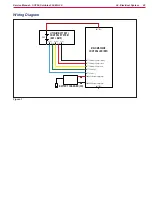
Страница 52: ...on System 52 Service Manual SC250 Scrubtec 334 MA 30 Wiring Diagram BATTERY BATTERY Water pump output OUT3 Water pump output OUT3 C 2 C 1 C 3 PM WATER SENSOR S3 WATER PUMP PM MAIN MACHINE CONTROLLER EB1 Figure 1 ...

Страница 53: ...ution tank assembly Tank filler cap Tank valve Solution filter Water Pump PM Hoses Water sensor S3 Solution dispenser to brush Solution tank assembly Figure 2 Solution tank filler plug Tank valve Figure 3 Water pump PM Tank filter Hoses Water sensor S3 Solution dispensers to brush area ...

Страница 54: ...ank and Filter 1 Ensure that the machine is off 2 Remove the tanks container from the machine body using the handle 3 Lift the tank cover and remove the solution cap 4 Rinse the tank out with water 5 Remove the rubber gasket A then remove the filter strainer B 6 Clean them carefully and reinstall C Figure 4 B A C ...

Страница 55: ...off 2 Remove the tanks container from the machine body using the handle 3 Lift the machine body to access the lower part of the cleaning deck 4 Remove the cylindrical brush 5 Disassemble the solution dispensers A and clean them with water and detergent then rinse and reassemble in the corresponding housings Figure 5 A A ...

Страница 56: ...n interrupted Replace the pump repair the electrical connection Presence of debris in solution tank blocking the outlet valve Clean the tank and the valve Main machine controller EB1 faulty Replace Main control board EB2 faulty Replace The solution reaches the brush also when the machine is off Dirt or scale in water pump PM or else it is broken Replace Water Pump Voltage and Cleaning Check Water ...

Страница 57: ...r pump faston connections C 5 With a digital multimenter D set to AC input E verify that on the output water pump C is current an alternating voltage of 14 16 V with activated water pump 6 If the water pump output is without voltage check in the order a Water pump wiring b Water pump efficiency Clean unlock or replace c Main machine controller efficiency Figure 7 C D E D ...

Страница 58: ...p duct F with the compressed air at 1 bar max for the Water pump removal see the procedure in Water pump removal installation paragraph Caution Blow with compressed air on the arrow direction as shown on the pump label 8 Eventually instead dissambling the Water pump blow the inlet on the solution filter compartment G use cloth to narrow the air flow Figure 8 F G ...

Страница 59: ...tec 334 MA 30 Removal and Installation Solution Tank Valve 1 Remove the tank assembly from the machine 2 Working at the workbench rotate the tank assembly and 3 Remove the 2 screws A remove the valve B and retain the gasket C for reuse Figure 6 C B A ...

Страница 60: ...ps A and remove the 7 screws B then remove the upper cover from the machine body C Figure 7 A B B B B B B B C A A A A A A 4 Disconnect the connection D and remove the Water pump E retaining the brackets and hoses for reuse Figure 8 D F E Installation 5 Install the components by performing the removal procedure in reverse ensuring you respect the flow direction arrow F on the Water pump ...

Страница 61: ...n the rear cover and remove the battery 3 Remove upper cover from the machine body A Figure 9 A 4 Remove the 2 screws A and lift the cover B off the sensor bracket 5 Disconnect the connection C and remove the water sensor D from the bracket Figure 10 A B C D Installation 6 Assemble the components in the reverse order of disassembly ...

Страница 62: ... SC250 Clarke MA 30 Nilfisk SC250 Scrubtec 334 Solution tank capacity 1 6 US gal 6 liters Min max solution flow 0 04 0 08 US gal min 0 15 0 3 L min Water pump technical data IP rating IP54 Maximum back pressure 0 8 bar Solution flow rate 21 L h Input power 18W Insulation class F Power consumption 900mA ...

Страница 63: ...ind the brush col lects small and medium sized debris picked up by the brush In the event of brush motor overload a safety system stops the brushes after about 25 seconds of continu ous overload The overload is detected by the Main machine control ler EB1 by monitoring the current flow to the brush motor Operation of the brush motor overload protec tion system is indicated by all 6 battery LEDs fl...

Страница 64: ...34 Scrub System 64 Service Manual SC250 Scrubtec 334 MA 30 Wiring Diagram BRUSH MOTOR M1 OUT1 Brush motor output BATTERY BATTERY OUT1 Brush motor output M1 MAIN MACHINE CONTROLLER EB1 Figure 1 ...

Страница 65: ...ocations Brush motor M1 Cylindrical brush Drive hub Driving belt Casing Floor brush pressure adjustment knob Debris collection tank Figure 2 Drive hub Brush motor M1 Debris collection tank Cylindrical brush Figure 3 Driving belt Floor brush pressure adjustment knob Casing ...

Страница 66: ...cleaning deck 4 Turn the lever counter clockwise A and remove the brush 5 Clean and wash the cylindrical brush with water and detergent 6 Check the brush bristles for integrity and wear if necessary replace the brush 7 Carefully clean the brush compartment B 8 Remove the debris collection tank C clean it and rinse it with clean water then put it back in its seat 9 Reinstall the cylindrical brush o...

Страница 67: ...rom rotating Clean the brush hub The brush does not turn Presence of bulky debris or string around the brush or between the brush and attachment flange Remove the brush and clean it While running the machine is noisy and it vibrates Deformed brush bristles Wash the brush with hot water to restore the bristles Do not leave the machine parked without the transport parking wheels The brush does not t...

Страница 68: ...Scrubtec 334 MA 30 Brush Motor Amperage Check Warning This procedure must be performed by qualified personnel only 1 Open the rear cover on the battery compartment 2 Remove the screw A and remove the controller protective cover B Figure 5 A B ...

Страница 69: ...h motor current draw is no more than 1 A at 36 V 6 If the current draw is higher check the belt tension or remove the brush motor see the procedure in the Vacuum System Motor Disassembly Assembly paragraph and check the condition of all its components to detect and correct the reason for the abnormal current draw If the above mentioned procedures do not produce the correct readings for the brush m...

Страница 70: ...the belt C to make sure it is intact and shows no signs of cuts tears or cracks replace if necessary 6 Check the tension of the belt C between motor and brush using the TEN SIT D device When deflecting the centre of the belt E the tool should measure a value of 69Hz 10 Belt tensioning If necessary tension the belt correctly C 7 Loosen the 3 screws F and adjust the position of the motor and pulley ...

Страница 71: ...ues Replacement 8 If the belt C requires replacement loosen the 3 screws F and move the brush motor and pulley G to loosen the belt then replace it 9 Tension the belt see the procedure given above Figure 9 C F F F F G G F F Reassembly 10 Perform steps 1 to 4 in the reverse order ...

Страница 72: ... cover and remove the battery 3 Remove the cylindrical brush 4 Remove the screw to remove the controller protective cover 5 Disconnect the brush motor connections A Do not loosen the connection fastening screws use a pair of pliers to hold the connector on the controller Figure 10 A 6 Remove the two cable retention clamps B Figure 11 B B ...

Страница 73: ...he machine body E Figure 12 C D D D D D D D E C C C C C C 8 Remove the screw F keeping the inner locknut G held in position Remove the 2 screws H keeping the inner locknuts I held in position Figure 13 H H F I I G 9 Working underneath the machine remove the clamp J and extract the wiring Remove the motor and transmission assembly K from the machine Figure 14 J K ...

Страница 74: ...ation 11 Fit the brush motor on its support and tension the belt 12 During assembly on the machine position the brush motor and keep it rotated as shown N then screw in and tighten the 3 screws O with the locknuts Figure 16 O O O N N 13 Assemble the components in the reverse order of disassembly Ensure the brush motor power supply cable polarity is correct on the connection to the main machine con...

Страница 75: ...Cylindrical brush diameter 3 in 80 mm Brush pressure on the ground Max 26 lb Max 12 Kg Brush motor technical data Power 0 24 hp 180 W Nominal speed 2000 140 rpm Nominal current draw 7 0 7 A Nominal torque 0 88 Nm No load current 0 5 0 3 A No load speed 2450 172 rpm Insulation class B IP rating IP20 Conductor and insulation materials UL certified Brush rotation speed 1 000 rpm ...

Страница 76: ...e machine body via two quick fix brackets fitted with springs which allow the squeegees to adhere to and apply the correct pressure to the floor even if it is not perfectly smooth and level Operating the right hand lever on the handlebar lifts the front squeegee allowing larger debris to be picked up The mechanism also stops vacuuming at the lifted front squeegee B with a consequent increase in va...

Страница 77: ...rated brackets with return spring for floor pressure Front right squeegee lifting lever Mechanism for front squeegee lifting and vacuum system stop Right lever Figure 2 Squeegee assembly Mechanism for front squeegee lifting and vacuum system stop Squeegee assembly Integrated brackets with return spring for floor pressure ...

Страница 78: ...system and can be easily removed 1 Ensure that the machine is off 2 Remove the tanks container from the machine body using the handle 3 Lift the machine body to access the lower part of the cleaning deck 4 Remove the squeegee bars by pulling them outwards 5 Clean and wash the squeegee bars In particular clean the compartments A and the vacuum hole B Check the blades for integrity cuts and tears if...

Страница 79: ...sufficient or there is no vacuuming The squeegee bars are dirty or the blades are worn or damaged Clean and check the squeegee bars The squeegees leave marks on the floor There is debris under the squeegee blades Remove the debris The squeegee blades are worn chipped or torn Replace the blades Debris collection tank full Empty the tank ...

Страница 80: ...al and Installation Vacuum Duct Removal 1 Remove the tank assembly from the machine 2 Open the rear cover and remove the battery 3 Remove upper cover from the machine body A Figure 4 A 4 Loosen the nut and locknut B and remove the squeegee lifting cable C Figure 5 C B ...

Страница 81: ...ct continues 5 Unscrew the 4 screws D and lift the vacuum duct bracket E Figure 6 E D D D D 6 Free the front hook F from the linkage G then remove the vacuum duct bracket E 7 Remove the vacuum duct H and check that the openings are free of dirt and debris Figure 7 H F E G ...

Страница 82: ...tallation 8 Install the vacuum duct making sure that the front I and rear openings J are correctly installed on the chassis Figure 8 J I 9 Fasten the front bar hook K to the squeegee lifting linkage L then fit the lifting cable M reinstalling the closing nut and locknut N Figure 9 M N K L ...

Страница 83: ... MA 30 Vacuum Duct continues 10 Adjust squeegee lifting Press the lifting lever and stop it with the orange push button 11 The minimum height of the lifting bar must be 0 7 in 18 mm O Adjust with the nut and locknut N Figure 10 O N 0 7 in 18 mm 0 7 in 18 mm ...

Страница 84: ...38 Squeegee System 84 Service Manual SC250 Scrubtec 334 MA 30 Specifications Description Model Advance SC250 Clarke MA 30 Nilfisk SC250 Scrubtec 334 Squeegee width 14 in 360 mm ...

Страница 85: ... airflow continues to the vacuum fan The automatic float in the vacuum grid on the cover stops the vacuum system motor M2 from collecting any liquid When the automatic float closes and stops the vacuum system the vacuum system motor noise will increase and the floor will not be dried The gasket on the input of the vacuum system motor allows full functionality of the system while the filter built i...

Страница 86: ...tomatic shut off float Recovery tank cover Cover gasket Vacuum grid with automatic shut off float Vacuum system motor M2 Vacuum system motor gasket Vacuum system motor filter Figure 2 Vacuum system motor M2 Figure 3 Cover gasket Recovery tank assembly Vacuum sleeves Recovery tank cover Vacuum system motor gasket and filter Vacuum grid with automatic shut off float ...

Страница 87: ...nd reinstall 5 Check the recovery tank cover gasket D for integrity Note The gasket D creates the vacuum in the tank that is necessary to vacuum up the recovery water 6 If necessary replace the gasket D by removing it from its housing on the cover When assembling the new gasket install the joint E in the area shown in the figure 7 Check the air duct gasket F conditions If necessary replace the gas...

Страница 88: ...ne body using the handle 2 Remove the air filter A and clean it 3 Refit the filter in the housing of the gasket B Note The gaskets B and C allow the creation of the vacuum in the system which is necessary to collect the recovery water 4 Check and clean the gasket B of the vacuum system motor 5 Check and clean the recovery water duct gasket C Figure 5 B A C ...

Страница 89: ...aw Replace Dirty water vacuuming is insufficient or there is no vacuuming Activation of automatic float shut off Drain the recovery tank Vacuum grid with automatic shut off float dirty Clean Tank cover not correctly positioned Adjust Tank cover gasket damaged or not working correctly Clean or replace The recovery water duct is dirty Clean the duct with running water The vacuum system motor contain...

Страница 90: ...334 MA 30 Vacuum System Motor Amperage Test Warning This procedure must be performed by qualified personnel only 1 Open the rear cover on the battery compartment 2 Remove the screw A and remove the main machine controller protective cover B Figure 6 A B ...

Страница 91: ...the vacuum system motor current draw is between 5 5 and 6 5 A at 36 V 6 If the current draw is higher remove the vacuum system motor see the procedure in the Vacuum System Motor Disassembly Assembly paragraph and check the condition of all its components to detect and correct the reason for the abnormal current draw If the above mentioned procedures do not produce the correct readings for the vacu...

Страница 92: ...y from the machine 2 Open the rear cover and remove the battery 3 Remove the screw to remove the controller protective cover 4 Disconnect the vacuum motor connections A Do not loosen the connection fastening screws use a pair of pliers to hold the connector on the controller Figure 8 A 5 Remove the two cable retention clamps B Figure 9 B B ...

Страница 93: ...inues 6 Turn the machine over onto its right side to access the lower area 7 Remove clamp C and clamp D to free up the wiring Figure 10 D C 8 Remove the wiring E from the machine 9 Unscrew the 4 retaining screws F and remove the vacuum motor unit G from the machine Figure 11 F G F E F F ...

Страница 94: ... System Motor continues Disassembly 10 At the workbench unscrew the 4 screws H then carefully rotate the vacuum system assembly 11 Remove the clamp I Figure 12 I H H H H 12 Lift the outer container J out of the inner container K then extract the motor L Figure 13 L J K ...

Страница 95: ...tinues 13 Save the gaskets M and N Figure 14 N M 14 Remove the save the clamp O and the dividing sponge P then disconnect the connections Q Figure 15 Q O P 15 Clean the inside of the containers to remove any dirt which has accumulated and check all gaskets for wear replace if necessary ...

Страница 96: ...ioned at 2 2 in 55 mm from the upper surface around the entire circumference Figure 16 R M 2 2 in 55 mm 18 Connect the power connections Q and position the gasket N below the vacuum system motor Check that the gasket is reassembled with the correct orientation 19 Position the sponge ring P flush against the clamp R Check that the wiring is inside the sponge ring and that the sponge is correctly or...

Страница 97: ...system motor in the outer container as shown S Figure 18 E S J 23 Rotate the outer container with the vacuum system motor Check that the motor and gasket are positioned almost in line with the outer edge of the container 24 Fit the inner container K and fasten it with the 4 screws Figure 19 K Installation 25 Continue to assemble the components in the reverse order of disassembly ...

Страница 98: ...ecovery tank capacity 1 6 US gal 6 liters Vacuum system motor technical data Power 0 24 hp 180 W Maximum current 6 0 3 A Maximum air flow 38 2 dm s Vacuum with Ø16mm hole 5 05 0 35 kPa A Insulation class H Impeller side bearing CW chemically resistant seal Conductor and insulation materials UL certified Vacuum system capacity 2 13 ft H2 O 650 mm H2 O ...

Страница 99: ...90 Options 99 Service Manual SC250 Scrubtec 334 MA 30 90 Options Description Illustration BATTERY AND BATTERY CHARGER KIT All versions Battery Battery charger Power supply cables ...

Отзывы: