36
- FORM NO. 56043122 - BR 1100S, 1300S
5 - SQUEEGEE SYSTEM
SQUEEGEE LIFT ACTUATOR REPLACEMENT
1
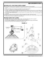
See Figure 5.2. Remove the Squeegee Tool
(A)
from the Squeegee Mount
(B)
.
2
Lower the squeegee mount to the
fl
oor by pressing the Vacuum Switch
(G)
on the control panel. Don’t turn the key switch off, until pushing apart the battery
Emergency Disconnect
(11)
. This procedure is done to prevent the squeegee mount from automatically raising when the key is turned off.
3
Unplug the squeegee lift motor wiring connector from the machine harness.
4
From underneath the machine remove the (2) Cotter Pins
(C)
and then slide out (push) both Mount Pins
(D)
from their mounting holes to complete the motor
removal from the machine.
Note:
New replacement lift actuator motors do not come with the lift nut pre-adjusted.
Important:
After removing the actuator motor and before replacing a new motor or drive nut the IN & OUT limit switches must be set (or checked) to their correct
speci
fi
cations (see the Electrical System for the Actuator Drive Nut Adjustment instructions).
5
After setting the correct actuator lift nut dimensions follow steps 1-4 in reverse order to re-install.
Service Tip Assembly Note:
Connect the special actuator power cord adapter (PN 56407502 shown in Electrical System
Actuator Drive Nut Adjustment)
to the lift
motor to help position the lift nut and mounting bracket for an easier installation.
SQUEEGEE MAINTENANCE
If the squeegee leaves narrow streaks of water, the blades may be dirty or damaged. Remove the squeegee, rinse it under warm water and inspect the blades.
Reverse or replace the blades if they are cut, torn, wavy or worn.
To Reverse or Replace the Rear Squeegee Wiping Blade...
1
See Figure 5.2. Raise the squeegee tool off the
fl
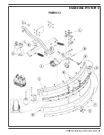
oor, then unsnap the Center Latch
(E)
on the squeegee tool.
2
Swing out Tension Straps
(F)
at both ends and disengage the straps’ slot from the front tool tension strap then remove.
3
Slip the Rear Blade
(G)
off the alignment pins.
4
The squeegee blade has 4 working edges. Turn the blade so a clean, undamaged edge points toward the front of the machine. Replace the blade if all 4 edges
are nicked, torn or worn to a large radius.
5
Install the blade, following the steps in reverse order and adjust the squeegee.
To Reverse or Replace the Front Squeegee Blade...
1
See Figure 5.2. Raise the squeegee tool off the
fl
oor, then loosen the (2) Thumb Nuts
(H)
on top of the squeegee and remove the squeegee tool from the
mount.
2
Remove both rear tension straps
fi
rst then remove all the wing nuts that hold the Front Blade
(J)
in place (shown in Figure 5.2), then remove tension strap and
blade.
3
The squeegee blade has 4 working edges. Turn the blade so a clean, undamaged edge points toward the front of the machine. Replace the blade if all 4 edges
are nicked, torn or worn to a large radius.
4
Install the blade, following the steps in reverse order and adjust the squeegee.
SQUEEGEE ADJUSTMENT
There are two major squeegee tool adjustments, height and angle. The recommended adjustment steps are to set the tool angle
fi
rst, then adjust the blade height.
Adjusting the Squeegee Angle
Adjust the squeegee angle whenever a blade is reversed or replaced, or if the squeegee is not wiping the
fl
oor dry.
1
Park the machine on a
fl
at, even surface and lower the squeegee. Then drive the machine forward enough to have the squeegee blades fold over to the rear
as shown in Figure 5.2 inset.
2
Turn the Adjustment Knob
(K)
to tilt the tool forward or backwards, until the rear squeegee wiping blade touches the
fl
oor evenly across its entire width.
Adjusting the Squeegee Blade Height
Adjust the squeegee height whenever a blade is reversed or replaced, or if the squeegee is not wiping the
fl
oor dry. The squeegee blade height is easily adjustable
at the caster wheels. To adjust...
1
Park the machine on a
fl
at even surface and lower the squeegee. Then drive the machine forward enough to have the squeegee blades fold over to the rear
as shown in Figure 5.2 inset.
2
Rotate the Adjustment Knobs
(L)
CW (clockwise) to lift the squeegee and CCW (counter clockwise) to lower it. A starting point when replacing the blades is to
adjust the caster-mounting bracket so it is level (parallel) to the top of the squeegee tool. Note: The Right and Left caster wheels must be adjusted equally to
maintain level and even blade pressure.
Содержание 56413006
Страница 7: ...FORM NO 56043122 BR 1100S 1300S 5 SPECIFICATIONS ...
Страница 9: ...FORM NO 56043122 BR 1100S 1300S 7 FIGURE 1 ...
Страница 10: ...8 FORM NO 56043122 BR 1100S 1300S THIS PAGE INTENTIONALLY BLANK ...
Страница 36: ...34 FORM NO 56043122 BR 1100S 1300S 4 RECOVERY SYSTEM FIGURE 4 2 ...
Страница 39: ...FORM NO 56043122 BR 1100S 1300S 37 SQUEEGEE SYSTEM 5 FIGURE 5 2 ...
Страница 47: ...FORM NO 56043122 BR 1100S 1300S 45 WHEEL DRIVE SYSTEM 6 FIGURE 6 5 ...
Страница 53: ...FORM NO 56043122 BR 1100S 1300S 51 REAR WHEEL SYSTEM 7 FIGURE 7 3 ...
Страница 61: ...FORM NO 56043122 BR 1100S 1300S 59 ELECTRICAL SYSTEM 8 J Ø 4 K Fault Indicator 03 FIGURE 8 7 ...


