background image

43

CONNECTIONS

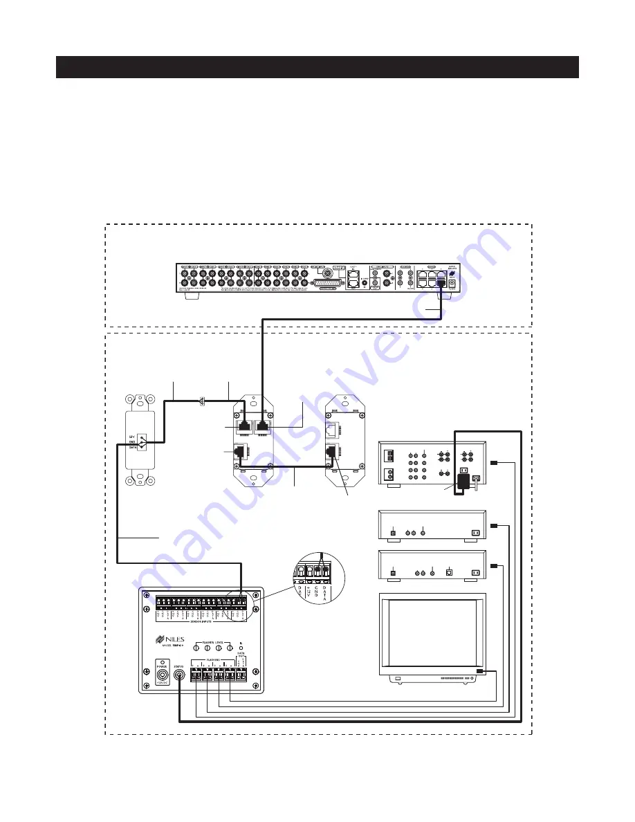
CONNECTING AN IR SENSOR FOR LOCAL SYSTEM CONTROL

IR Sensors installed in zones for hand-held IR remote control of the A4.6Ci and its connected source compo-
nents can also be used to control local components (i.e., a TV, DSS, DVD, and a surround-sound system locat-
ed in the master bedroom zone as shown in Figure 38).

The IR sensor connects normally to the Solo

and Select

Master Keypad to control the A4.6Ci and its con-

nected source components. In addition, the IR sensor connects to a local IR repeating system (DATA and GND
connections only) to provide control of local components.

TV

Four-Pair Twisted Cable

L

R

AUDIO VIDEO

DSS

PHONE

DIGITAL

L

R

AUDIO VIDEO

DVD

RECEIVER

DIGITAL

L

R

AUDIO

CD

DVD

Video 3

Video 2

Video 1

VIDEO

FRONT

L

L

R

DIGITAL

1

2

R

CENTER

REAR

L

R

12V
D.C.

Niles IRP-6+

(provided for IR control 

of local equipment)

Zone 6 – Master Bedroom

Distributed Equipment Location

Plugged into 

Switched AC outlet

Niles 

IRR-4D+

IR Sensor

Solo

Master 

Keypad Module

RJ-45 Connector 
for connection to 
Numeric Accessory 
Keypad Module

RJ-45 Connector 
for connection to 

Master Keypad 

Module

RJ-45 Connector 
for connection to 
IR Sensors

Two-Conductor Shielded Cable
(connect DATA and GND only)

Two-Conductor 

Shielded Cable

Three-Wire to 

RJ-45 Adapter

RJ-45 Connector for 

connection to 

the A4.6Ci

Included 

Jumper Cable

IR SENSOR

INPUT

OUTPUT

SYSTEM

ACCESSORY 

KEYPADS

Figure 38

Содержание A4.6Ci

Страница 1: ...I N S T A L L A T I O N O P E R A T I O N G U I D E A4 6Ci A4 6Ci MultiZone Audio Preamplifier B L E N D I N G T E C H N O L O G Y A N D A R C H I T E C T U R E Four Source Six Zone Preamplifier ...

Страница 2: ...S 7 PARTS GUIDE 9 A4 6Ci 10 IntelliPad Ci Keypad Modules 11 R 4 Remote Control 12 SYSTEM CONFIGURATIONS 13 Configuration 1 Six Zones 13 Configuration 2 Adding Zones Using Multiple A4 6Ci s 15 Configuration 3 Integrating an IR Controlled Home Theater 16 Configuration 4 Integrating a Home Theater using an Intellicontrol 17 Configuration 5 Multiple Master Keypad Modules in a Zone 18 Configuration 6 M...

Страница 3: ...unction Key Button Operation 34 identical Source Components 35 Shared Source Components 35 Operating a System with Multiple A4 6Ci s 35 Operation from the Stereo Zones Provided by the A4 6Ci 36 Operation from the Home Theater Zone 36 System Busy Indication 37 Paging Indication 37 INSTALLATION 38 CONNECTIONS 39 Terminating Four Pair Twisted Cable 39 Connecting the Solo or Select Master Keypads to t...

Страница 4: ...Programming Panel 45 Installation and Programming Documentation 46 System Installation Schematics 49 System Programming Worksheets 55 Programming a Learning Remote for Zone Operation Using Keypad Modules 61 Programming a Learning Remote for Zone Operation Using the Niles R 4 Remote Control 62 Programming a Home Theater Remote to Operate Source Components Shared with an A4 6Ci 62 INSTALLATION SETTI...

Страница 5: ...NG STEPS 88 Edit Source Component Power 88 Edit Input Selection 88 Function Key IR Programming 89 Edit Master Key Sequence Programming 90 Edit Zone and System ON OFF Sequence Programming 91 Edit Function Key Sequence Programming 93 Program Erasing 94 Transferring IR Configuration Programs Between A4 6Ci s 97 ACCESSORIES 98 TROUBLESHOOTING 102 SPECIFICATIONS 103 5 TABLE OF CONTENTS ...

Страница 6: ...ion you have been asking for It allows you to combine Keypad Modules with Infrared Sensors and Hand Held Remotes for total control of your Home Entertainment System providing one touch system wide control Now everyone in the household can be happy One person can listen to the CD player in a bedroom while another simultaneously listens to the radio by the pool At the same time a third person can li...

Страница 7: ...or complete control of your distributed A V system Sync Inputs provided by the A4 6Ci sense wether the connected source components are ON or OFF Power commands for these source components are issued only if the source components are actually OFF turning them on correctly every time The proper input for the source component is then selected and a programmed sequence of IR commands is issued i e pla...

Страница 8: ...This signal can be interfaced to voltage triggered AC power strips i e Niles AC 3 for the automation of source components that can only be activated via switched AC outlets Expandable for Larger Multi Zone Systems Up to four A4 6Ci s can be combined in a single system providing 24 zones Source component audio signals are shared between preamplifiers utilizing the buffered cascade audio outputs pro...

Страница 9: ...nterface Sensor for Capturing IR Commands Programming Controls and Indicators Figure 4 A4 6Ci Rear Panel 16V DC Power Input Keypad Inputs Flasher Outputs 12V Control Output IR Input Sync Inputs System Expansion DB25 Zone Audio Output Paging Input Audio Inputs with Buffered Cascade Outputs Zone Audio Outputs Figure 2 A4 6Ci Front Panel with Programming Cover Figure 2 A4 6Ci Front Panel with Program...

Страница 10: ...h is designed for the IRC 1P Flood Flasher Keypad Inputs Six female RJ 45 jacks are used for the connection of the IntelliPad Ci Master Keypad Modules Audio Inputs with Buffered Cascade Output Four pairs of stereo RCA jacks provide input connec tions for source components Each input has a respective buffered cascade output for distributing audio signals for expanded systems DB25 Zone Output A DB 2...

Страница 11: ...ee seconds turns on all enabled zones Also all zones are selected to the same source component Zone OFF Key A quick tap of this Key turns your specific ZONE OFF Pressing and holding this button for longer than three seconds causes ALL ZONES to turn OFF Volume Keys A continuous press of these buttons raises or lowers the volume in your specific ZONE Pressing these but tons also restores sound in a ...

Страница 12: ...nds causes all zones to turn off Function Buttons Pressing these buttons issues the individual IR com mands programmed for control of the connected source components Zone Volume Buttons A continuous press of these buttons raises or lowers the volume in your specific zone Pressing these buttons also restores sound in a muted zone Zone Mute Button A quick tap of this button mutes the sound in a zone...

Страница 13: ... individual volume level If more than one zone chooses the same source component IR control of that source component is shared between the zones 13 CONFIGURATION 1 SIX ZONES SYSTEM CONFIGURATIONS I N F R ARE D SE N S O R K N OCK OU T I N F R ARE D SEN S O R K N OCK OU T ZONE 1 I N F R ARE D SE N S O R K N OCK OU T I N F R ARE D SEN S O R K N OCK OU T ZONE 2 I N F R ARE D SE N S O R K N OCK OU T I ...

Страница 14: ...t Automation There are two methods of controlling the power ON OFF of the source components 1 Synchronized IR In Figure 4 the DSS receiver s power ON OFF is synchronized via a video signal con nected to the A4 6Ci When the Master Key Source Button for the DSS is pressed the A4 6Ci checks for a video signal at the Sync Input corresponding to the DSS The A4 6Ci issues the power command to turn the D...

Страница 15: ... Preamplifiers share the audio signal from the source components via the buffered cascade audio outputs provided one for each of the four audio inputs Source component control is accomplished via the programming in the Master A4 6Ci All Slave A4 6Ci s in the system are left unprogrammed except for Zone On Off Sequences and the required function key IR pro gramming to create these sequences All Fla...

Страница 16: ... A4 6Ci with the On Off status of the Home Theater This status enables the A4 6Ci to provide coordinated control of the source compo nent s power On Off Important Note When issuing the source component s actual IR commands from the Home Theater Remote Control all IR commands are passed through to all source component flasher outputs Identical brand and model source components cannot be operated in...

Страница 17: ...details on page 45 A 12V Sync signal is provided from the IntelliControl to the Home Theater Sync Input to provide the A4 6Ci with the On Off status of the Home Theater This status enables the A4 6Ci to provide coordinated control of the source component s power On Off Important Note When issuing the shared source components actual IR commands from the Home Theater Remote Control all IR commands a...

Страница 18: ...a single zone using two Expanders In Figure 11 two Solo Master Keypad Modules are installed on either side of a bed When connected all keypads in a zone work in tandem with one another i e all control the same zone and display the same Zone ON OFF Mute and Input Select Status SYSTEM CONFIGURATIONS 1 2 3 OUTPUT POWER INPUTS Unswitched AC Outlet DB 25 Cable Niles IntelliPad Ci Expander Power Supply ...

Страница 19: ...each area A Niles IntelliPad Ci Expander is required to connect the two Solo Master Keypad Modules in a single zone When connected all keypads in a zone work in tandem with one another i e all control the same zone and display the same Zone ON OFF Mute and Input Select Status 19 SYSTEM CONFIGURATIONS I N F R A R E D S E N S O R K N O C K O U T I N F R A R E D S E N S O R K N O C K O U T I N F R A ...

Страница 20: ...zone amplifier Connection of three rooms with Master Keypads and Silencers to a single zone of the A4 6Ci is accomplished with a single Niles Expander Five rooms is accomplished using two Expanders see the Expander manual for more details SYSTEM CONFIGURATIONS I N F R A R E D S E N S O R K N O C K O U T I N F R A R E D S E N S O R K N O C K O U T I N F R A R E D S E N S O R K N O C K O U T I N F R...

Страница 21: ...lephone systems for voice paging through the speakers located in the listening zones see Figure 14 A Niles AVDA 3 see Figure 15 is required when connecting a telephone system to two or more A4 6Ci s in larger systems 21 SYSTEM CONFIGURATIONS PAGE OUTPUT Telephone Control Unit System Telephones Figure 14 PAGE OUTPUT Telephone Control Unit System Telephones Niles AVDA 3 Distribution Amplifier Figure...

Страница 22: ...f an identical brand and type component in both the local and the distributed system i e a Sony CD player in both systems is not supported by this configuration Individual operation of identi cal components may not be possible refer to Connections section Audio signals for the shared source components are connected to the Home Theater receiver using the cascade audio outputs SYSTEM CONFIGURATIONS ...

Страница 23: ...same system it is advisable to first test how these components interact with each other To test for this type of conflict take all the remotes in the system and issue every command you will be pro gramming in the keypads Expose all components to each command and make sure that only the appropriate component responds Solving the IR Command Conflict if Present Remember that conflicts of this nature ...

Страница 24: ...of the source components It allows synchronization via voltage and video signals seeChoosingaSynchronizationMethodon page25 formoreinformation on howto synchronizecomponents Source Components that Do Not Require Synchronization Two types of components do not require synchronization Those with separate ON and OFF IR commands and those with latching power Source Components with Separate ON OFF IR Co...

Страница 25: ...component synchronization The A4 6Ci has three 12V Video Sync connections for synchronizing as many as three source components In Figure 18 the video output of a DSS is connected to both a TV and the corresponding sync input for the DSS using an RCA Y adapter Picture quality will be unaffected due to the high impedance of the sync input If the source component has two video outputs the need for an...

Страница 26: ...ger when it is turned ON When it senses that change it outputs a 12V DC signal The synchronized CD changer s AC power plug is connected to the current sensing outlet on the APC 2 The APC 2 s 12V DC output is connect ed to the A4 6Ci s sync input dedicated to the CD changer using a Niles 10 bare wire to mini plug accessory cable FG00724 see Accessories for more details When using a Niles APC 2 a mi...

Страница 27: ...tal source component also can provide a light source for sync using the LS 1 SOURCE AND HOME THEATER SYNC STATUS Sync status the presence or absence of a valid sync signal of source components and the Home Theater associated with the Master A4 6Ci are displayed on the LEDs located in the hidden programming panel These LEDs illuminate only while a valid sync signal is being received by the A4 6Ci d...

Страница 28: ...r Key 3 Source Button 3 and Master Key 4 Source Button 4 The eight available Master Keys and their corresponding four Source Buttons are individually programmable Once programmed they operate the system identically in each zone Note Master Keys on the Solo and Select Master Keypad Module should be labeled the same in each zone OPERATIONAL OVERVIEW Source Buttons on the Hand Held R 4 Remote Accesso...

Страница 29: ...e inputs are selected every time a Master Key is pressed or pressed and held Event 4 The Source Power event is programmable with IR commands individually for each Master Key IR commands taught to the Master Keys assigned to inputs 1 and 2 are issued conditionally and based on the presence of a sync signal at the corresponding sync port Event 5 The System ON Sequence event is programmed with IR com...

Страница 30: ...mming DIP switches set individually for each zone All zones enabled for ALL ON Page select the source associated with the Master Key Source Button pressed and held and that same Master Key LED illuminates GREEN Zones responding to system wide commands turn ON to a default volume This volume can be individually adjusted for each zone see the programming section of this manual for details OFF KEY OF...

Страница 31: ...ith multiple rooms within the zones Important Note When a zone has more than one room a Niles Silencer Volume Control and Master Keypad Module are required in each room within the zone to provide individual ON OFF and volume adjustment Following is an operational description for zones with one room and zones expanded into multiple rooms using Silencers A Zone with One Room Individual Room Operatio...

Страница 32: ...uing the All OFF command and Event 2 occurs for all other zones sequentially Additionally Events 3 and 4 occur if the Home Theater that shares sources is also OFF VOLUME KEYS VOLUME BUTTONS The volume keys on the Solo and Select Master Keypad Module and the volume buttons on the R 4 Remote provide control of volume for individual zones VOLUME KEYS VOLUME BUTTONS OPERATION Pressing the Volume or th...

Страница 33: ...ne is MUTED If a zone has more than one Master Keypad Module but has no silencers all the Master Keypad modules always illuminate identically In a zone including many rooms with silencers the Mute Key mutes and unmutes the silencer for that room only The system considers the room to be ON while the zone is muted The Master Key lights GREEN while the room is ON and RED while the room is MUTED A mut...

Страница 34: ...for a connected source component has been pressed the A4 6Ci activates a zone and selects that source component The individual Function Keys Buttons in that zone will now issue the IR commands that have been programmed for the selected source component A sequence of IR commands and or delays can be issued when a Function Key Button is programmed with a Function Key Button Sequence 34 OPERATIONAL O...

Страница 35: ...2 and System Configuration 3 for more details OPERATING A SYSTEM WITH MULTIPLE A4 6Ci s Operating a system with multiple A4 6Ci s is the same as operating a system with only one A4 6Ci Solo or Select Master Keypad Modules in each zone independently operate the zone to which they are dedicated i e Zone ON OFF Volume Up Down Mute When a user in a zone from any A4 6Ci presses a key button the IR comm...

Страница 36: ...operate individually with this method Also when using this method reliable activation of shared source components that use a sin gle IR command for power ON OFF is not possible Refer to Method 2 for operating identical shared source components and components with a single IR command for power ON OFF When the Home Theater turns ON it provides a 12V status signal that is connected to the Home Theate...

Страница 37: ... source components that are unique in the system may have their actual IR com mands programmed into the Home Theater remote and issued for simple IR repeating using this method When the Home Theater is turned OFF the Home Theater remote sends a Niles OFF command to the A4 6Ci The A4 6Ci then checks all zones for all A4 6Ci s in the system If all zones are OFF the 12V control output shuts OFF turni...

Страница 38: ...idelity component the A4 6Ci will last much longer if it receives adequate ventilation for proper cooling see Figure 28 38 OPERATIONAL OVERVIEW Make sure that there is a minimum of 1 of free air space above the preamplifier and 1 on each side for proper ventilation Allow a minimum of 2 of depth behind unit to accommodate cables and connectors Figure 28 ...

Страница 39: ...olo Master Keypad Module Numeric Accessory Keypad Module RJ 45 Connector for connection to Master Keypad Module RJ 45 Connector for connection to Numeric Accessory Keypad Module RJ 45 Connector for connection to IR Sensors RJ 45 Connector for connection to the ZR 4630 Included Jumper Cable IR SENSOR INPUT OUTPUT SYSTEM ACCESSORY KEYPADS Figure 32 Figure 33 CONNECTING NUMERIC KEYPADS Each Solo and ...

Страница 40: ...connection to Numeric Accessory Keypad Module RJ 45 Connector for connection to IR Sensors Four Pair Twisted Cable RJ 45 Connector for connection to the ZR 4630 Figure 34 1 1 12V 3 GND 2 DATA 2 3 4 Pair 2 Pair 1 T568A Pair 3 Pair 4 5 6 7 8 Figure 35 Figure 36 Niles IRR 4D IR Sensor Solo Master Keypad Module RJ 45 Connector for connection to Numeric Accessory Keypad Module RJ 45 Connector for conne...

Страница 41: ... refer to page 39 SOURCE COMPONENT POWER AND HOME THEATER SYNCHRONIZATION SIGNALS 5 12V Home Theater Sync to Home Theater Sync Input The 12V Home Theater sync signal connects with a mini plug to the Home Theater sync input 6 Video Synchronization from a Source Component to an A4 6Ci Sync Input An RCA Y adapter is used to split the video output of a source component for connection to one of the two...

Страница 42: ... Accessory Cable FG00724 connects a Home Theater control system to the IR input 12V CONTROL SIGNALS 1 12V Control Output to a Voltage Triggered Device The mini plug end of a Niles Accessory Cable FG00724 connects the 12V control output to the trigger input of a voltage activated device i e Niles AC 3 IR FLASHERS 1 Low Output Flasher to the Flasher Outputs The mini plug end of a Niles Low Output Mi...

Страница 43: ...s TV Four Pair Twisted Cable L R AUDIO VIDEO DSS PHONE DIGITAL L R AUDIO VIDEO DVD RECEIVER DIGITAL L R AUDIO CD DVD Video 3 Video 2 Video 1 VIDEO FRONT L L R DIGITAL 1 2 R CENTER REAR L R 12V D C Niles IRP 6 provided for IR control of local equipment Zone 6 Master Bedroom Distributed Equipment Location Plugged into Switched AC outlet Niles IRR 4D IR Sensor Solo Master Keypad Module RJ 45 Connecto...

Страница 44: ...A4 6Ci connects to the A side of the SPK 1 The main speaker output of the local system connects to the B side of the SPK 1 In addition a 12V DC power adapter Niles FG00665 is plugged into a switched AC outlet of the local system to activate the SPK 1 Zone 6 Master Bedroom Distributed Equipment Location I N F R ARE D SE N S O R K N OCK OU T I N F R ARE D SE N S O R K N OCK OU T I N F R ARE D SE N S...

Страница 45: ... with the source components see Figure 41 A Niles hand held R 4 Remote can be used instead of a connected Master Keypad Module see Figure 42 For complete information on the A4 6Ci s step by step programming procedure refer to the Programming Steps section of this manual 45 PROGRAMMING OVERVIEW Figure 42 Niles hand held R 4 Remote Control sold separately Source Components IR Remote Control supplied...

Страница 46: ...SSORY MODULES NUMERIC TRANSPORT IR SENSOR ZONE 5 ZONE NAME SOLO SELECT INPUT EXPANDER OPTIONAL ACCESSORY MODULES NUMERIC TRANSPORT IR SENSOR ZONE 6 ZONE NAME 5 PAGING DEVICE YES NO SOURCE 11 ZONE OUTPUT RCA DB 25 1 3 4 2 ZONE AMPLIFIER 5 6 SOURCE 10 CASCADE OUTPUT YES NO 1 3 4 2 SOURCE DESTINATION 9 MASTER A4 6Ci 1 3 4 2 ZONE ALL ON PAGE 5 6 6 SOURCE 4 SYNC INPUTS 1 VIDEO 12V 7 HOME THEATER SYNC Y...

Страница 47: ...EY 2 MASTER KEY LABEL ________ ASSIGNED SOURCE INPUT 1 2 3 4 MASTER KEY 4 MASTER KEY LABEL ________ ASSIGNED SOURCE INPUT 1 2 3 4 MASTER KEY 6 MASTER KEY LABEL ________ ASSIGNED SOURCE INPUT 1 2 3 4 MASTER KEY 8 MASTER KEY LABEL ________ ASSIGNED SOURCE INPUT 1 2 3 4 Source IR Power Programming and Master Key Setup Figure 45 Worksheet 1 INTELLIPAD Ci EXPANDER INSTALLATION SCHEMATIC MULTI AREA ZONE...

Страница 48: ...E DESCRIPTION 1 2 3 4 5 ZONE ON SEQUENCE KEY PROGRAMMING WORKSHEET 5 ZONE ON OFF AND SYSTEM ON OFF SEQUENCE PROGRAMMING 1 JOB TITLE 2 SYSTEM DESIGNER STEP PAGE DESCRIPTION 1 2 3 4 5 ZONE OFF SEQUENCE KEY STEP PAGE DESCRIPTION 1 2 3 4 5 ZONE ON SEQUENCE KEY STEP PAGE DESCRIPTION 1 2 3 4 5 ZONE OFF SEQUENCE KEY STEP PAGE DESCRIPTION 1 2 3 4 5 ZONE ON SEQUENCE KEY STEP PAGE DESCRIPTION 1 2 3 4 5 ZONE...

Страница 49: ...ERVIEW 1 JOB TITLE 2 SYSTEM DESIGNER Document the customer s name Document the system designer s name Mr Smith John Doe 3 4 SOURCE 3 1 2 FLASHER AUDIO INPUTS BRAND MODEL SOURCE A B C D SOURCE 4 SYNC INPUTS 1 VIDEO 12V SYNC 2 TYPE VIDEO 12V SOURCE YES NO YES NO 5 PAGING DEVICE YES NO Ci Net CONNECTIONS FROM TO 6 7 HOME THEATER SYNC YES NO HOME THEATER IR YES NO Your system can have up to four sourc...

Страница 50: ...S NUMERIC TRANSPORT IR SENSOR ZONE 3 ZONE NAME SOLO SELECT INPUT EXPANDER OPTIONAL ACCESSORY MODULES TRANSPORT IR SENSOR ZONE 4 ZONE NAME SOLO SELECT INPUT EXPANDER OPTIONAL ACCESSORY MODULES NUMERIC TRANSPORT IR SENSOR ZONE 5 ZONE NAME SOLO SELECT INPUT EXPANDER OPTIONAL ACCESSORY MODULES NUMERIC TRANSPORT IR SENSOR ZONE 6 ZONE NAME NUMERIC FROM EXPANDER FROM EXPANDER FROM EXPANDER FROM EXPANDER ...

Страница 51: ... B With a second expander the zone can have up to five keypads The top input of Expander A connects to the A4 6Ci keypad input With a single expander connect keypads for Areas 1 2 and 3 to the remaining inputs When a second expander is required connect Expander B to the bottom input of Expander A Connect keypads for Areas 1 and 2 to Expander A and key pads for Areas 3 4 and 5 to Expander B MASTER ...

Страница 52: ...ander the zone can have up to five keypads The top input of Expander A connects to the A4 6Ci keypad input With a single Expander connect keypads for Rooms 1 2 and 3 to the remaining inputs When a second expander is required con nect Expander B to the bottom input of Expander A Connect keypads for Room 1 and 2 to Expander A and keypads for Room 3 4 and 5 to Expander B MASTER KEYPAD MODULE CHOOSE O...

Страница 53: ...____ Document the origin of audio inputs for the four sources For example if this were Slave 2 Source 1 would come from Slave 1 If it were Slave 1 the source would come from the Master To ensure accuracy check the information in this box against the information documented under Cascade Output in box 10 for the Master Schematic sheet and in box 8 for the Slave Schematic sheet Paging device YES NO T...

Страница 54: ...pecify where the cascade output is going for example a Home Theater or the next Slave preamp in the system To ensure accuracy check the information in this box against the information documented under Cascade Input box 4 for the Slave Schematic sheet Also note that the Home Theater is always the last to receive the shared audio signals in multi zone systems Indicate if using either RCA or DB 25 to...

Страница 55: ...Single Power IR Command Two Separate ON and OFF IR Commands Latching Power SOURCE 1 and SOURCE 2 Transfer the information in box 3 and box 4 of the Master Preamp Schematic to identify the brand and model of each source then indicate if the components have sync yes no and if yes the sync type video 12V Power programming Check if single power IR command two separate ON OFF IR commands or latching po...

Страница 56: ...igure 46 documents the IR commands programmed into the Master A4 6Ci These commands control the components and build sequences regardless of whether the sequences will be used to operate the sources in the system On Off sequence or in any of the zone On Off sequences for the Master A4 6Ci 56 PROGRAMMING OVERVIEW 1 JOB TITLE 2 SYSTEM DESIGNER Document the customer s name Document the system designe...

Страница 57: ...et 3 are to be used in the zone On Off sequences for their respective Slave A4 6Ci 57 PROGRAMMING OVERVIEW 1 JOB TITLE 2 SYSTEM DESIGNER Document the customer s name Document the system designer s name Mr Smith John Doe PAGES FUNCTION KEYS Label all Master Key Pages 1 8 as assigned in box 4 for Worksheet 1 1 PAGES KEYS FUNCTION KEYS 1 2 3 4 5 6 7 8 9 0 RANDOM GROUP Document the IR commands stored ...

Страница 58: ...nding Sequences that can be built are for the Master A4 6 and you may have as many as eight Copy the worksheet as needed 58 PROGRAMMING OVERVIEW 1 JOB TITLE 2 SYSTEM DESIGNER Document the customer s name Document the system designer s name Mr Smith John Doe STEP PAGE DESCRIPTION MASTER KEY 1 KEY 1 2 3 4 5 6 7 8 9 10 The steps in the Master Key Ending Sequence for Master Keys 1 8 Describe the IR co...

Страница 59: ...e customer s name Document the system designer s name Mr Smith John Doe CHOOSE ONE MASTER SLAVE 1 SLAVE 2 SLAVE 3 ZONE 3 Check a box to indicate if it is the Master or Slaves 1 3 Zone number STEP PAGE DESCRIPTION 1 2 3 4 5 ZONE ON SEQUENCE KEY STEP PAGE DESCRIPTION 1 2 3 4 5 ZONE OFF SEQUENCE KEY 3B The steps in the Zone On and Zone Off sequences Describe the IR commands or indicate if there are d...

Страница 60: ... sequence so the sequence only gets issued whenever that key is pressed 60 PROGRAMMING OVERVIEW 1 JOB TITLE 2 SYSTEM DESIGNER Document the customer s name Document the system designer s name Mr Smith John Doe 3 FUNCTION KEY SEQUENCES Indicate the trigger page and the trigger key The Trigger Key is the Function Key that will initiate the sequence when pressed The Trigger Page is the Master Key page...

Страница 61: ...four flasher outputs Step 2 Connect a keypad to the preamp s front panel Step 3 Press and hold the TEST IR button The Page LED and the Key LED blink RED to indicate you are in the teaching mode Step 4 Press the Function Key or Master Key that you are going to teach It is important to note the following 1 Tapping a Master Key sends one command 2 Pressing and holding a Master Key sends a different c...

Страница 62: ...a zone The OFF Button to turn off the zones To teach these commands set the learning remote that you will use in the zone to the learning mode choose the appropriate key on the learning remote and then issue the appro priate command from the Niles R 4 Remote Repeat these steps for the remaining commands you wish to use To test the commands set the Niles remote aside and try the commands on your le...

Страница 63: ... source components using this method and is done in con junction with programming described Method 2 Controlling Shared Source Components with Niles R 4 Commands and 12VHome Theater Status A second method of programming a Home Theater remote control is available when the shared source components are identical and or they have a single power ON OFF IR command With this method you teach the Niles Co...

Страница 64: ...ter Keys 1 8 and the OFF Button IR commands Whenever the Master A4 6Ci receives a source button IR command from the Home Theater it will turn on the source com ponent if needed and it will also know that the Home Theater zone is turning on and what source compo nent is selected Whenever the Master A4 6Ci receives an OFF button IR command from the Home Theater it will know that the Home Theater is ...

Страница 65: ... are designed to be placed in the zone label slots to identify the names of each of six zones To install these labels follow the steps below 1 Remove the label chosen for Zone 1 from the included room zone labels 2 Affix the label in Zone Label Slot 1 3 Repeat steps 1 and 2 for Zones 2 through 6 VOLUME SETTINGS The A4 6Ci has three useful volume settings Maximum Turn ON and Source Change Volume Le...

Страница 66: ...s and hold the ZONE SELECT button Once in the installer setting mode you can perform three functions Manual operation of individual zones Preamplifier output mode setting Acoustic adjustments MANUAL OPERATION OF INDIVIDUAL ZONES The A4 6Ci can be operated manually from the front panel to test the preamplifier if a zone suddenly stops playing or if it doesn t activate after the system is installed ...

Страница 67: ...which you wish to change modes for continue to tap ZONE SELECT until the LED for the desired zone starts blinking Step 3 Press the ON button to turn the zone ON The Power LED indicates the current preamplifier output mode GREEN for Variable and RED for Fixed Step 4 Press the Next Button to toggle the select ed zone to the desired mode fixed mode is cho sen when multiple rooms are included in a zon...

Страница 68: ...4 Master Key 4 lights up indicating it is ready to adjust balance Step 13 Use the Volume Up key for the right speaker and the Volume Down key for the left Loudness Zones are set to loudness OFF as the default Step 14 When using Solo keypads tap the Arrow Up key to turn loudness ON Important Note When using a Solo keypad mod ule you must press any one of the Master Keys prior to setting Loudness Th...

Страница 69: ... and OFF commands to Inputs 3 and 4 These inputs do not have sync Set Up 1 Remove the programming cover to reveal the programming panel 2 Connect a Master Keypad into the keypad input to the far right of the panel POWER COMMANDS Step 2 Press a Master Key where you want to program source component power IR commands Important Note Every Master Key that activates a source component with IR must be pr...

Страница 70: ...s the appropriate power or ON button on the original factory remote Step 4 Press the OFF button on the original factory remote if the component has discrete ON and OFF commands The ENTER IR LED turns OFF and the PAGE LED blinks RED Or press the PROGRAM button if the component has one power command for both ON and OFF The ENTER IR LED turns off and the PAGE LED blinks RED ...

Страница 71: ...al programming or If the command fails to operate the source component press the same Master Key again to erase the IR command automatically Step 7 Repeat steps 2 through 6 until you have successfully captured the IR command s Note that you need to capture both ON and OFF again if the component has discrete power commands Step 8 Press the next Master Key to program Repeat steps 2 through 7 for the...

Страница 72: ... press PROGRAM to assign it The INPUT LED turns off and the PAGE LED blinks RED Step 4 Repeat steps 1 through 3 until all Master Keys have been assigned their appropriate inputs INPUT ASSIGNMENT Step 1 Press a Master Key to assign one of the four audio inputs corresponding to the source component that Master Key will activate It doesn t matter how the input assignment is ordered For example I can ...

Страница 73: ...ands stored to the various Function Keys Each Function Key can store one IR command per available Master Key Page The PAGE LED turns off and the KEY LED blinks RED To program function keys within the Default Page tap the OFF Key Master Keys 1 and 3 illuminate To program function keys within the Library Page press and hold the OFF key Master Keys 1 3 and 4 illuminate simulating an L Step 2 Press th...

Страница 74: ... or be intermittently solid RED to reflect real time IR activity during IR transmission and then turn OFF again Step 5 If the command fails to operate the source component press the same Function Key you are programming The IR command is automatically erased If the command successfully operates the source component continue programming Step 6 You can continue programming other Function Keys for th...

Страница 75: ...Function Keys have been programmed for all the Master Key Pages When all the necessary Function Key IR commands have been programmed press NEXT to continue programming The POWER MASTER KEY SEQ LED turns ON GREEN the TRIGGER LED turns ON RED and the PAGE LED blinks RED MASTER KEY SEQUENCE Step 1 Press a Master Key to program the Master Key Sequence The TRIGGER LED turns OFF and the PAGE continues t...

Страница 76: ... you are programming or Tap the OFF Key if the IR command is in the Default Page or Press and hold the OFF key if the IR command is in the Library Page The PAGE LED turns OFF and the KEY LED blinks RED Step 3 Press the Function Key where the IR command is stored The KEY LED turns OFF and the PAGE LED blinks RED Select Transport Numeric Select Transport Numeric ...

Страница 77: ...delay time Refer to the table below DELAY TABLE KEY Master Key 1 DELAY TIME 5 seconds Master Key 2 1 seconds Master Key 3 4 seconds Master Key 4 8 seconds For example if you press Master Key 2 a one second delay is added to the sequence After you choose a delay all Master Keys turn OFF The KEY LED turns OFF and the PAGE LED blinks RED Step 6 To add another delay press the DELAY button again and re...

Страница 78: ... 1 through 8 until all Master Key Sequences have been programmed Note If you missed IR commands in a sequence re do the programming for the whole sequence When you reach step 3 and press the actual Function Key that triggers the sequence whatever was previously programmed for that key is auto matically erased To erase programming after it has been saved see Erasing Programming Step 10 Press NEXT t...

Страница 79: ...equence Step 2 Press the ZONE ON button to program the Zone ON Sequence for the desired zone or to program the System ON Sequence if you have selected all zones Or press the ZONE OFF button to program the zone off for the desired zone or to program the system OFF sequence if you have selected all zones The INPUT 1 LED turns on The INPUT 4 LED turns on The selected zone s LED stops blinking and tur...

Страница 80: ...links RED Select Transport Numeric or Tap the OFF Key if the IR com mand is stored in a Function Key within the Default Page Master Keys 1 and 3 illuminate or Press and hold the OFF Key if the IR command is stored in a Function Key within the Library Page Master Keys 1 3 and 4 illu minate simulating an L Step 4 Press the Function Key where the IR command is stored The KEY LED turns OFF and the PAG...

Страница 81: ... Select Transport Numeric Step 6 To insert delays press the DELAY button instead of a Master Key while the PAGE LED is blinking RED The PAGE LED turns off the KEY LED blinks RED and the first four keys on the Master Key module illuminate Step 7 Choose the Master Key for the desired delay time Refer to the table below DELAY TABLE KEY Master Key 1 DELAY TIME 5 seconds Master Key 2 1 seconds Master K...

Страница 82: ... can have two consecutive one second delays Step 9 Repeat steps 3 through 8 Zone ON OFF and System ON OFF sequence to continue identifying the Master Key Pages where the IR commands are stored for all the steps in the Zone On Off or System On Off sequence you are programming Step 10 Press the PROGRAM key to program a different Zone On Off or System On Off sequence The ZONE 1 LED blinks GREEN the T...

Страница 83: ...aced Step 12 Press NEXT to continue programming The FUNCTION KEY IR FUNCT KEY SEQ LED is on GREEN the TRIGGER LED is on RED and the PAGE LED is blinking RED FUNCTION KEY SEQUENCE Step 1 Press a Master Key to identify the Master Key Page where the Function Key that triggers the sequence is located The TRIGGER LED remains ON the PAGE LED turns OFF and the KEY LED blinks RED Select Transport Numeric ...

Страница 84: ... LED turns OFF Select Transport Numeric Step 3 Press the Master Key that identifies the Master Key Page or tap the OFF Key for the Default Page or press and hold the OFF Key for the Library Page where the IR command is stored for the first step in the Function Key Sequence The PAGE LED turns OFF and the KEY LED blinks RED Select Transport Numeric ...

Страница 85: ...he KEY LED turns off and the PAGE LED blinks RED Select Transport Numeric Step 5 To insert delays press the DELAY button instead of a Master Key while the PAGE LED is blinking RED The PAGE LED turns off the KEY LED blinks RED and the first four keys on the Master Key Module illuminate ...

Страница 86: ...med all the steps in the Function Key Sequence Step 9 Press the PROGRAM button to program a sequence for a different Function Key within the same Master Key Page The TRIGGER LED turns on RED the PAGE LED turns off and the KEY LED blinks RED Step 6 Choose the Master Key for the desired delay time Refer to the table below DELAY TABLE KEY Master Key 1 DELAY TIME 5 seconds Master Key 2 1 seconds Maste...

Страница 87: ...age Step 11 Press the PROGRAM button twice to program sequences within other Master Key Pages The TRIGGER LED turns on RED the PAGE LED blinks RED Step 12 Repeat steps 1 through 11 until you have programmed all the Function Key Sequences for all Master Key Pages Step 13 Press the PROGRAM button three times to save and exit the Programming Mode ...

Страница 88: ...ess the TEST button If it does not operate the component as expected teach and test the command again until it does Note Repositioning the remote control when teaching the command can assist in capturing commands accu rately Step 6 If there are other Master Keys to edit press the appropriate Master Key and then repeat steps 3 through 5 until you have edited all the power commands Step 7 Press Next...

Страница 89: ...and the KEY LED blinks RED Step 4 Press the Function Key you are editing The KEY LED turns off and the ENTER IR LED turns on RED Step 5 Press the appropriate command on the original factory remote The ENTER IR LED turns OFF and the KEY LED blinks RED Step 6 To test the command s press the TEST button If it does not operate the component as expected teach and test the command again until it does No...

Страница 90: ... off and the KEY LED blinks RED Step 5 Press the function key where the IR command is stored The KEY LED turns off and the PAGE LED blinks RED Step 6 You can now identify the Master Key Page where the IR command is stored for the second step in the Master Key Sequence you are editing Note If the sequence includes a DELAY i Press the DELAY button instead of a function key while the PAGE LED is blin...

Страница 91: ...NE AND SYSTEM ON OFF SEQUENCE Step 1 Press and hold the PROGRAM button Step 2 Press the NEXT button four times The INPUT ZONE SYS SEQ LED turns on GREEN the TRIGGER LED turns on RED and the PAGE LED blinks RED The LED for Zone 1 blinks GREEN indicating that Zone 1 is selected by default Step 3 To edit a sequence for a zone other than Zone 1 press the Zone Select button until the LED for the desire...

Страница 92: ... the PAGE LED is blinking RED The PAGE LED turns off and the KEY LED blinks RED The first four keys on the Master Key Module illuminate ii Choose the Master Key for the desired delay time Refer to the table below For example if you press Master Key 2 a one second delay is added to the sequence After you choose a delay all Master Keys turn off The KEY LED turns OFF and the PAGE LED blinks RED iii P...

Страница 93: ...r To edit a sequence to a Function Key located within the Library Page press and hold the OFF Key Master Keys 1 3 and 4 illuminate simulating an L This indicates that you are selected to the Library Page The TRIGGER LED remains on the PAGE LED turns off and the KEY LED blinks RED Step 4 Press the Function Key to edit The TRIGGER LED turns off the PAGE LED blinks RED and the KEY LED turns off Step ...

Страница 94: ...Step 11 Press the PROGRAM button to save and exit programming Note If you missed IR commands in a sequence re do the programming for the whole sequence PROGRAM ERASING Individual IR commands can be erased at the time you are programming them See the steps for each event for specific information on how to test IR commands and erase them at that time whenever necessary The information in this sectio...

Страница 95: ...pressed any command stored for that key is erased Step 1 Press and hold the PROGRAM key to enter Program Mode The POWER MASTER KEY SEQ LED turns on RED and the PAGE LED blinks RED Then press the NEXT button twice The FUNCTION KEY IR SEQ LED turns on RED and the PAGE LED blinks RED Step 2 Press the appropriate Master Key tap the OFF Key or press and hold the OFF key on the Master Keypad to identify...

Страница 96: ... address where the individual commands are stored Instead press the PROGRAM key to erase the sequence and exit Step 1 Press the PROGRAM button once then the NEXT button four times The INPUT ZONE SEQ LED turns on GREEN the TRIGGER LED turns on RED and the PAGE LED blinks RED Step 2 The Zone 1 LED blinks to indicate that Zone 1 is selected by default The LEDs for the remaining zones are off To erase...

Страница 97: ...onfiguration may have its program contents transferred to a second A4 6Ci Step 1 Connect one end of a DB 9 null modem cable pins 2 and 3 reversed and pin 5 to 5 to the A4 6Ci that contains the configuration you wish to transfer Refer to this A4 6Ci as the output unit Step 2 Connect the other end of that DB 9 null modem cable to the A4 6Ci to which you wish to transfer the configuration Refer to th...

Страница 98: ...d buttons are programmable and capable of automating multiple commands with the single touch of a button so you can create custom presets or scenes Custom label your master keys to match your system or favorite preset over 200 labels included The Niles MultiZone Control System monitors the status of your components and automatically shuts down your entire system with the single touch of a button f...

Страница 99: ...ED confirms the reception of an IR com mand or possible IR interference Sensor pick up range 25 30 Miniature size makes it virtually invisible Circuit board s Surface Mount Technology SMT assures high reliability Includes a 6 hook up wire Overall dimensions 3 4 dia x 2 3 8 deep Bezel dimensions 3 4 dia x 1 4 deep Approximate shipping weight 1 lb MS 2 IR MicroSensor ColorStock White FG00627 Black F...

Страница 100: ...omponents in your system should have their power status synced to the A4 6Ci The following accessories either sense that a component is on off or actually turn the component s on off APC 2 Current Sensing Outlet Switcher STOCK FG00254 Current sensing outlet Provides 12V DC sync connection via an accessory cable to the IntelliControl IPC 6 Programmable AC Power Controller LS 1 Light Sensor SENSITIV...

Страница 101: ...onvenience outlets are available separately in our Jobsite System Modular Connector Plate Kit with Handy Carrying Case STOCK FG00872 The complete one box solution for all your con venience outlet needs this connector plate man agement kit is complete with assorted Decora style insert modules to accommodate any wall plate configuration necessary for DSS TV tele phone computer and audio video instal...

Страница 102: ...e Niles IRR 4D Wall Mount or the Niles TIR 1 Tabletop IR sensors the Status LED should be illuminating GREEN when the zone is on The Status LED should be off when the zone is off and RED when receiving a command When using the Niles MS 1 or MS 2 IR sensors the Status LED should be off when the zone is ON It should only illuminate GREEN when receiving an actu al IR command If the LEDs stay constant...

Страница 103: ...evel 1 Vrms Signal to Noise Ratio 90 db at 1Vrms output Crosstalk 90 db at 1Vrms between zones channels Input Impedance 10k ohms paging 100k ohms Input Sensitivity 330 mv input for 1V out with zero db control gain paging 10 mv input for 1V out Maximum Hum 90 db Channel Balance 20 hz 20 khz 0 5 db Tone Control Range 14 db 100 hz 14 db 15 khz Power Requirements 16V DC 1 5a Net Weight w xf 10 65 lbs ...

Страница 104: ...104 NOTES ...

Страница 105: ...105 NOTES ...

Страница 106: ...port are trademarks of Niles Audio Corporation All other trademarks are property of their respective owners See documentation inside packaging for further legal notices Printed in USA DS00274B Niles Audio Corporation 12331 S W 130 Street Miami FL 33186 Mailing Address P O Box 160818 Miami FL 33116 Customer Service 1 800 BUY HIFI 1 800 289 4434 Phone 305 238 4373 Fax 305 238 0185 Visit us on the we...

Страница 107: ...Signal to Noise Ratio 90dB at 1Vrms output Crosstalk 90dB at 1Vrms between zones channels Input Impedance 10k ohms paging 30k ohms Input Sensitivity 330mV input for 1V output with zero dB control gain paging 550mV input for 1V output Maximum Hum 90dB Channel Balance 20Hz 20kHz 0 5dB Tone Control Range 14dB 100Hz 14dB 15kHz Power Requirements 16V DC 1 5A Net Weight w xf 10 65 lbs Dimensions 17 wide...

Отзывы: