


2 – COMPOSITION
SPDM CONTROL BOX
NIDEC ASI S.P.A. – SPDM CONTROL BOX USER MANUAL
26
IMSPDCB2EN
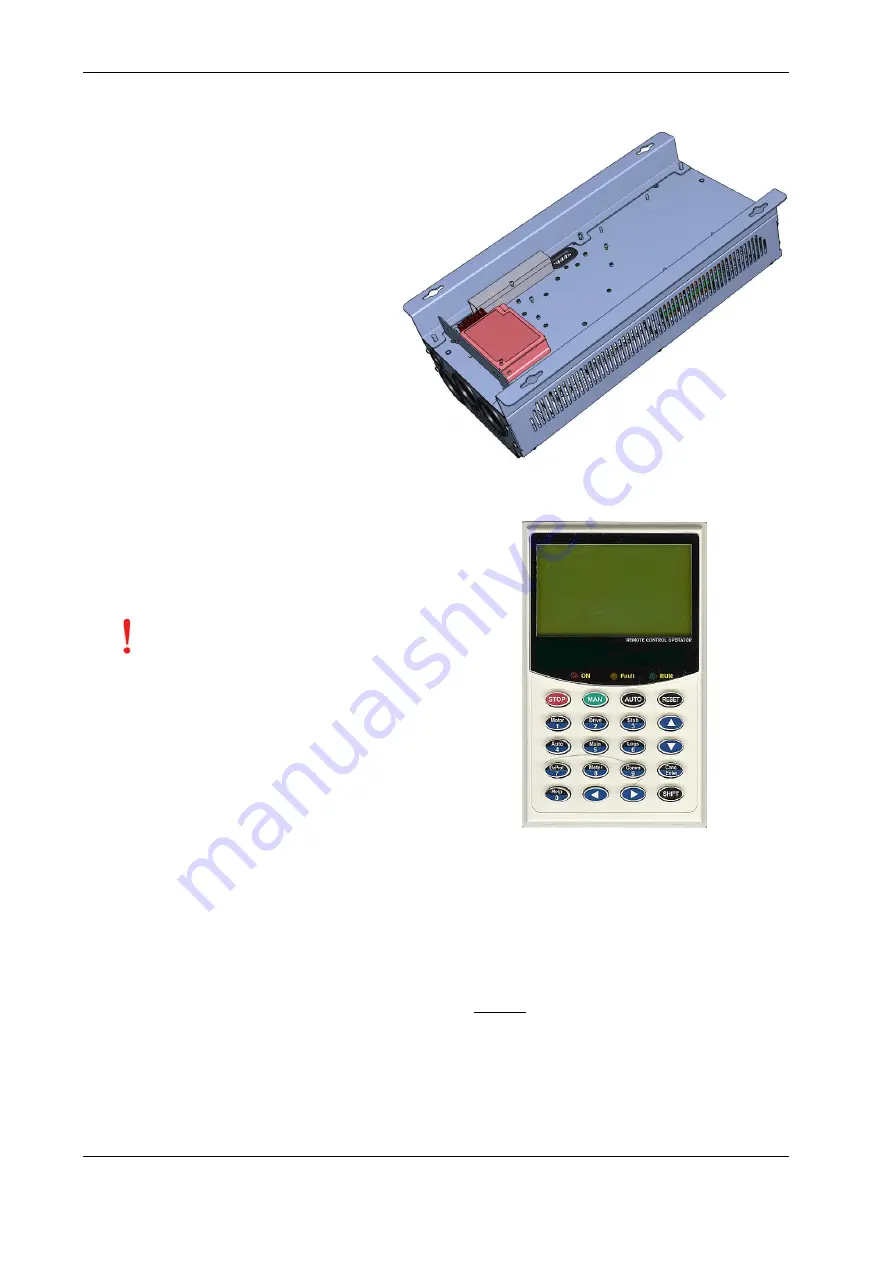
Switched Mode Power Supply (cod. 8000002668)
2.9
The voltage at 24V for the GAAPA board is obtained
from a switching mode power supply (SMPS) installed on
the bottom side of the back of the control box.
The input voltage of the power supply is 110÷240V ac ,
50÷60Hz single phase.
The output voltage is 24Vdc, 2.2A.
To permit proper airflow and dissipate the heat produced
by the power supply, leave a minimum clearance as
suggested in paragraph 5.2.
Keypad (cod. 8000001597)
2.10
The connection of the keypad to the SYSTEM2 control requires a
standard Ethernet network cable, like those normally used for
network connections. The communication cable shall be connected
on the control card to the connector (RJ45 type) called “COM”.
ATTENTION:
Near
the
connector
“COM”
(reserved for keypad) there is the
connector “ETH” dedicated to the
Ethernet connection.
The wrong
connection of the keypad to the
connector called “ETH” can
damage the control board.
Encoder Interface “SYSENC”
2.11
2.11.1
General data
Accurate speed control needs an incremental encoder installed on the motor shaft (zero impulse is not necessary for standard applications).
Encoders with whatever pulses/revolution (PPR) and either line driver or push-pull electronic circuit can be used.
Maximum input frequency of the control card: f
MAX
= 100KHz.
Termination resistor for encoder line-driver: 120Ω
Maximum input frequency and the number of pulses per revolution (PPR) of the encoder determine the maximum measurable speed:
ܯ ܽݔܵ݁݁݀
[
ܴܲܯ
] =
݂
ெ
∙ 60
ܴܲܲ
The SYSENC has two terminals for the feeding the encoder at 5V (max 100mA) or 24V (max 150mA).
If a higher power level is needed to supply the encoder, provide an external power supply unit that should be mounted as close as possible to
the encoder.


