Nice E MAT MT 1517 Скачать руководство пользователя страница 6

4

 – English

EN

The electrical connections must be made only after installing the motor and compat-

ible accessories required.

The electrical cord of the motor is made up of the following internal cables (

fig. 3

):

Cable colour 

connection

1


White-black 

shared for bus wires

2


White 

TTBUS / Counter-clockwise rotation pushbutton

3


White-orange  Clockwise rotation pushbutton

4


Brown 

Power supply phase

5


Blue Neutral

6


Yellow-green Earth

4.1 - Connection of motor to electricity mains

Utilise cords 4, 5, 6 (

fig. 3

) to connect the motor to the main and pay attention to 

the 

warnings

:

–  improper connection can cause breakdowns and hazardous situations;

–  scrupulously respect the connections indicated in this manual;

–  in the power supply network of the motor you must install a disconnection device 

having an opening distance of the contacts that allows complete disconnection 

in the overvoltage category III conditions, in conformity with the installation rules 

(disconnection device not supplied with the product).

4.2 - Connection of accessories to motor

Accessories can be connected by cable

: use cables 1, 2, 3 (

fig. 3

) to connect 

the accessories to the motor; refer to 

fig. 3

 of Chapter 6 - “Optional Accessories” 

and pay attention to the following 

warnings

:

–  Cables 1, 2, 3 of the bus lines MUST NOT be connected to be electrical mains.

–  To the White + White-black lead you can connect only one accessory at a time 

from among the compatible ones.

–  To the White- White-black lead you can connect only one accessory at a 

time from among the compatible ones.

–   The Open and Flows inputs are constrained to reach other, in other words they 

must be used with the same pushbutton strip (

fig. 3

). As an alternative, if only the 

White lead is available, you can use the step-by-step input.

Accessories can be connected by a radio

 (portable transmitters and certain cli-

matic sensor models): memorise these accessories in the motor during the program-

ming phases; refer to the procedures given in this manual and those given in the 

manuals supplied with the devices.

ac

ELECTRICAL CONNECTIONS AND

FIRST POWER UP

4

ac

5.1 - General warnings

• The limit switch must be adjusted after installing the motor in the awning and con-

necting it to the power supply.

• In cases of installations with several motors and/or receivers, before starting to 

program you must disconnect the electrical supply to the motors and receivers you 

do not wish to program.

• Scrupulously respect the time limits indicated in the procedures: after releasing a 

key, you have 60 seconds to press the next key indicated in the procedure; other-

wise, when the time is up, the motor will perform six movements to communicate 

cancellation of the procedure in progress.

• During programming, the motor performs a certain number of brief movements, 

as a “response” to the command sent to the installer. It is important to count the 

number of these movements without considering the direction in which they are 

performed.

• Every time the motor is powered, 2 movements are performed if at least one trans-

mitter and the limit switch heights are not in the memory.

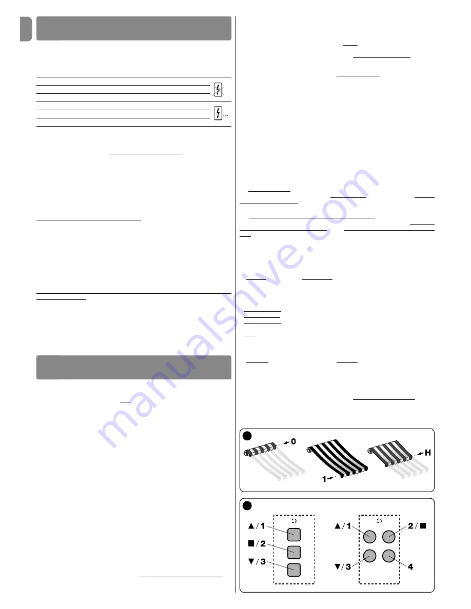
5.2 - Positions in which the awning stops  

automatically

The electronic system that controls the awning movement at all times can automati-

cally stop the movement when the awning reaches a certain position programmed 

by the installer. The programmable positions are (

fig. 5

):

– position “

0

” = upper limit switch: totally wound awning;

– position “

1

” = lower limit switch: totally unwound awning;

– position “

H

” = intermediate position: partially open awning.

When the limit switches are not programmed yet, the awning can be moved only in 

the “hold-to-run” mode, i.e. keeping the control key pressed for the desired duration 

of the manoeuvre; the movement stops as soon as the user releases the key. How-

ever, after programming the limit switches, briefly pressing the appropriate key will 

start the awning and it will stop moving automatically as soon as the awning reaches 

the required position.

PROGRAMMING AND ADJUSTMENTS

5

5

6

To adjust the distances “

0

” and “

1

” various procedures are possible; to choose the 

appropriate one, take into account the supporting structure of your awning (see the 

summary in the table).

WARNING! – If you want to again adjust again the height of the limit switch-

es adjusted previously, consider the following:

– If you would like to adjust them with an alternative procedure different 

from the one used previously, you must FIRST delete the heights by follow-

ing procedure 5.16.

– If you wish to adjust them with the same procedure used previously, you 

need not delete them.

The programming of the limit switches simultaneously combines the two directions 

of rotation of the motor to the respective shutter raising key (

s

) and shutter lowering 

key (

t

) of the control device (initially, when the limit switches are not programmed 

yet, the combination is random and it can happen that when pressing the 

s

 key, the 

shutter moves down instead of up, or vice versa).

5.3 - Overview of the transmitters

5.3.1 - Compatible transmitters

Consult the Hunter Douglas product catalogue to find the Hunter Douglas devices 

compatible with the radio receiver built into the motor.

5.3.2 - Transmitter memorisation hierarchy

In general a transmitter can be memorised as a FIRST transmitter or a SECOND 

transmitter (or third, fourth, etc.).

A - First transmitter

A transmitter can be memorised as a first transmitter only if in the motor no other 

transmitter is memorised. For this memorisation, follow procedure 5.5 (this memo-

rises the transmitter in “Mode I”.

B - Second (or third, fourth, etc.) transmitting device

A portable transmitter (or a radio climate sensor) can be memorised as a second (or 

third, fourth, etc.) transmitting device only if the First Transmitter is already memo-

rised in the motor. For this memorisation, follow one of the procedures given in sec-

tion 5.10.

5.3.3 - Two procedures to memorise the keys of a transmitter

To memorise the keys of a transmitter, two different procedures can be used: “Mode 

I” and “Mode II”.

• “

MODE I

” – This mode automatically transfers, the various commands available 

in the motor, all together, into the various keys available on the transmitter, without 

allowing the installer to change the combinations of commands and keys. Upon 

completion of the procedure, each key will be combined with a command according 

to the following diagram.
- key 

s

 (or key 

1

): will be combined with 

Raise

- key 

n

 (or key 

2

): will be combined with the command 

Stop

- key 

t

 (or key 

3

): will be combined with the command 

Lower

(if there is a fourth key on the transmitter .....)

- key 

4

: will be combined with the command 

Stop

Note

 – If the keys of your transmitter have no symbols or numbers, see 

fig. 6

 to 

identify them.

• “

MODE II

” – This mode allows you to manually combine one of the commands 

available in the motor with one of the transmitter keys, giving the installer the option 

of choosing the command and key combinations to use. At the end of the proce-

dure, to memorise another key with another command desired, it will be necessary 

to repeat the procedure once again.

Warning!

 – Each automation has its own list of commands that can be memorised 

in Mode II; in the case of the present motor the list of commands available is given 

in procedure 5.10.2.

Содержание E MAT MT 1517

Страница 1: ...rnings for installation and use SV Anvisningar och s kerhetsf reskrifter f r installation och anv ndning E MAT ST 324 E MAT ST 524 E MAT ST 611 E MAT ST 1011 E MAT MT 817 E MAT MT 1517 E MAT MT 3017 E...

Страница 2: ......

Страница 3: ...5 sec 2 1 01 5 sec 03 05 THE END 07 04 5 sec 02 0 2 4 06 1 5 sec 3 5 sec 01 04 03 02 5 sec 5 sec all data 05 THE END 5 sec 5 sec 2 3 3 3 5 Turn OFF Wait Turn ON Movements no 2 Press until Movements no...

Страница 4: ...the limit switches it is compatible with all Hunter Douglas electronic control components transmitters and climate sensors that use the NRC radio system it can be controlled by radio or by cable using...

Страница 5: ...t be 52 mm INSTALLATION OF THE MOTOR AND THE ACCESSORIES 3 for motors that are size M 45 mm and have a torque of up to 35 Nm included the minimum inside diameter of the winding roller must be 60 mm fo...

Страница 6: ...partially open awning When the limit switches are not programmed yet the awning can be moved only in the hold to run mode i e keeping the control key pressed for the desired duration of the manoeuvre...

Страница 7: ...graph 5 7 Programming in manual mode paragraph 5 6 Adjustment of the motor traction force RDC function paragraph 5 12 with automatic stop in the upper limit switch position 0 with box without containm...

Страница 8: ...rform 4 movements Upon completion release the key 03 Keep the s key pressed and wait for the motor to perform two movements Upon completion release the key 04 Adjustment of the position keep the s or...

Страница 9: ...stroke 01 Run the UP command by keeping the s or t key pressed and wait for the awning to stop automatically as result of the impact against the structure upper limit switch 0 Upon completion release...

Страница 10: ...ings closings each called H height These heights can only be adjusted after adjusting limit switches 0 and 1 The following procedure makes it possible to adjust one H height at a time Warnings If you...

Страница 11: ...transmitter in Mode II regardless of the Mode in which the old to transmitter was memorised 01 on the new transmitter Hold the key to be memorised down for 8 seconds for example the n key then releas...

Страница 12: ...n completion release the key 01 02 5 sec THE END 03 5 sec 2 1 2 3 4 5 10 sec 0 5 sec x 1 forza massima x 2 forza medio massima x 3 forza media x 4 forza medio minima x 5 forza minima 3 Note When perfo...

Страница 13: ...ing the canvas taut To unlock the awning first send a short Down command to manually remove the lock and finally send an UP command to the awning Warning The FTA function may be programmed exclusively...

Страница 14: ...th the manual procedure paragraph 5 6 if the awning does not have a box or with the semiautomatic procedure paragraph 5 7 if the awning has a box How to program position S this position is programmed...

Страница 15: ...d previously Keep the n key pressed and wait for the motor to perform 5 movements Upon completion release the key 5 sec 01 04 03 02 5 sec 5 sec all data only 05 05 THE END 0 1 H 05 THE END THE END 5 s...

Страница 16: ...se the key 04 Keep the s and t keys pressed simultaneously and wait for the motor to perform 2 movements Upon completion release the keys 05 To unlock the memory Keep the s key pressed and wait for th...

Страница 17: ...lease the key 04 Keep the n key pressed and wait for the motor to perform 2 movements Upon completion release the key 05 To assign the Open command to a pushbutton Keep the s key pressed and wait for...

Страница 18: ...rted the manual commands are deactivated and it is not possible to open the awning At the end of the barring period the manual commands are reactivated and after 15 minutes the automatic operation is...

Страница 19: ...sence absence of rain not raining starting to rain stopped raining system deactivated system deactivated after 3 seconds system active active manual commands after 15 minutes sensor dry 8 5 0 10 15 20...

Страница 20: ...perates in the emergency condition with an operator present Check to see if the motor has undergone a significant thermal or mechanical shock Make sure each part of the motor is still in good conditio...

Страница 21: ...5 THE END 07 04 5 sec 02 0 2 4 06 1 5 sec 3 5 sec 01 04 03 02 5 sec 5 sec all data 05 THE END 5 sec 5 sec 2 3 3 3 5 Sl fr n V nta Sl till R relser nr 2 Tryck till R relser nr 3 Sl pp upp Slut Slut Slu...

Страница 22: ...t skydda elkablar Om n tkabeln skadas under installationen kan inte produkten anv ndas eftersom kabeln inte kan bytas ut och skadan kan utg ra en fara Vid montering av systemet se till att inga person...

Страница 23: ...ter vara minst 52 mm INSTALLATION AV MOTORN OCH TILLBEH R 3 F r motorstorlek S 45 mm ska upprullningsrullens inv ndiga diameter vara minst 60 mm F r motorstorlek S 58 mm ska upprullningsrullens inv nd...

Страница 24: ...en av procedurerna som beskrivs i avsnitt 5 10 5 3 3 Tv procedurer f r att memorera knapparna p en s ndare F r att memorera knapparna p en s ndare kan tv olika procedurer anv ndas L ge I och L ge II...

Страница 25: ...gesbrytare 0 om det finns automatiska hakar vid den nedre gr nsl gesbrytaren 1 om det finns manuella hakar eller bultar den nedre gr nsl gesbrytaren 1 det r n dv ndigt att minska st tkraften vid st ng...

Страница 26: ...nta tills motorn g r tv r relser Sl pp sedan upp knappen 04 Inst llning av positionen H ll s knappen eller t knappen nedtryckt tills markisen n r nskad 0 h jd Obs F r att st lla in h jden med precisi...

Страница 27: ...la s knappen eller t knappen nedtryckt och v nta tills markisen stoppas automatiskt n r den st ter emot stommen vre gr nsl gesbrytare 0 Sl pp sedan upp knappen 02 K r NED kommandot genom h lla s knapp...

Страница 28: ...an hantera upp till 30 ppningar st ngningar till h lften som vardera kallas f r H h jd Dessa h jder kan endast st llas in efter inst llningen av gr nsl gesbrytare 0 och 1 Med f ljande procedur kan man...

Страница 29: ...en nya s ndaren i L ge II oavsett i vilket l ge den gamla s ndaren memorerades 01 P den nya s ndaren Tryck ned knappen som ska memoreras i 8 sekunder t ex n knappen och sl pp sedan upp den i detta fal...

Страница 30: ...tills motorn g r 3 r relser Sl pp sedan upp knappen 01 02 5 sec THE END 03 5 sec 2 1 2 3 4 5 10 sec 0 5 sec x 1 forza massima x 2 forza medio massima x 3 forza media x 4 forza medio minima x 5 forza m...

Страница 31: ...sa upp markisen skicka f rst ett kort NED kommando f r att frikoppla l sanordningen manuellt och skicka sedan ett UPP kommando till markisen Varning FTA funktionen kan endast programmeras efter att g...

Страница 32: ...dem igen med den manuella proceduren avsnitt 5 6 om markisen inte har en kassett eller med den halvautomatiska proceduren avsnitt 5 7 om markisen har en kassett Hur man programmerar position S Denna...

Страница 33: ...en nedtryckt och v nta tills motorn g r 5 r relser Sl pp sedan upp knappen 5 sec 01 04 03 02 5 sec 5 sec all data only 05 05 THE END 0 1 H 05 THE END THE END 5 sec 5 sec 5 sec 2 3 3 3 5 5 5 Obs Du kan...

Страница 34: ...p sedan upp knappen 04 H ll s och t knapparna nedtryckta och v nta tills motorn g r 2 r relser Sl pp sedan upp knapparna 05 L sa upp minnet H ll s knappen nedtryckt och v nta tills motorn g r 3 r rels...

Страница 35: ...l en tryckknapp H ll t knappen nedtryckt och v nta tills motorn g r 5 r relser Sl pp sedan upp knappen 04 05 THE END 05 THE END 5 sec 5 sec 5 sec Open command Step by step command 5 sec 01 03 02 5 sec...

Страница 36: ...n automatiska funktionen 6 2 2 4 Prioritet f r atmosf riska h ndelser och funktionsprioritet f r Sol Regn och vind sensorer Prioritetsskalan f r atmosf riska h ndelser r f ljande 1 Vind 2 regn och 3 s...

Страница 37: ...jar regna slutar regna nedre tr skelv rde hysteres vre tr skelv rde nedre tr skelv rde vindpust hysteres vre tr skelv rde aktiva manuella kommandon efter 15 minuter system inaktiverat system inaktiver...

Страница 38: ...n r gr nsl gesbrytaren med maximal precision Denna funktion aktiveras inte n r slaget av markisen r kortare n 2 5 sekunder och inte n r gr nsl gesbrytaren 7 3 ppna st nga markisen till h lften h jd H...

Страница 39: ......

Страница 40: ...www niceforyou com Nice SpA Oderzo TV Italy info niceforyou com IS0226B00MM_26 07 2017...

Отзывы: