background image

GreenMaster-HP 4-16/30, 5-16/30

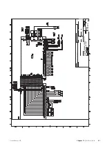
Part Specification Sheet      051190-0

Page 2/10 Created:2017-03-22 15:47

0.001

MJN

MJN

400V 3N~ 50Hz, 16+30kW

WIRING DIAGRAM GM-HP-16-30 ELSCHEMA GM-HP-16-30

051190

0

89

Chapter 11 |

Technical data

GreenMaster-HP

Содержание AirSite GreenMaster-HP 3-12/12

Страница 1: ...Installer manual UN GreenMaster HP 3 12 12 3 16 12 3 16 15 4 16 12 4 16 15 4 16 20 4 16 30 5 16 30 Exhaust air heat pump for properties IHB EN 1901 2 431719 ...

Страница 2: ......

Страница 3: ... medium side 22 Water heater 23 5 Electrical connections 23 General 24 Connections 26 Optional connections 31 Connecting accessories 32 6 Commissioning and adjusting 32 Preparations 32 Flushing 33 Pressure and leakage tests 34 Cleaning and filling 35 Post adjustment and venting 37 7 Control menus 37 Start guide 37 Menu system 39 8 Service and maintenance 39 Service 47 9 Disturbances in comfort 47 ...

Страница 4: ... personal injury Installation without sufficient support can also cause vibrations and noise Ensure that the unit is stable when installed so that it can withstand earthquakes and strong winds Unsuitable installation locations can cause the unit to fall and cause material damage and personal injury The electrical installation must be carried out by a qualified electrician and the system must be co...

Страница 5: ...ny buttons with wet hands This can cause electric shocks Do not touch any refrigerant pipes with your hands when the system is in operation During operation the pipes become extremely hot or extremely cold depending on the method of operation This can cause burn injuries or frost injuries Do not shut off the power supply immediately after operation has start Wait at least 5 minutes otherwise there...

Страница 6: ... section Heat exchanger section Fan section Pressure sensor exhaust air duct Integral water seal Flue gas extraction option Exhaust air damper option Brine Non return valves System flushed System vented Antifreeze Filterball particle filter Safety valve Shut off valves Circulation pump setting Heating medium Non return valves System flushed System vented Expansion vessel Filterball particle filter...

Страница 7: ...otes Description Fuses GreenMaster HP Fuses property Outside sensor Room sensor Current sensor Safety breaker Earth circuit breaker Setting of emergency mode thermostat 7 Chapter 1 Important information GreenMaster HP ...

Страница 8: ...eather and impacts The packaging must be removed and the unit covered with a tarpaulin or similar To ensure that there is as little condensation as possible good circulation must be guaranteed between the protective cover and the unit Separable version due to narrow transport routes If the unit is to be moved into a fan room in properties where the transport route is narrow or where it is not poss...

Страница 9: ...n carrying the unit by hand All parts of the unit weigh more than 20 kg and have to be carried by at least two people Wear safety gloves to minimise the risk of cuts Caution Before dismantling note which parts are loc ated where in order to make assembly easier 1 Open the covers on the lower sections 2 Disconnect all electrical quick couplings Roll up the cables one by one and secure them with a c...

Страница 10: ...vessel to the stay 17 Lift off the heat exchanger section NOTE Take care not to damage the pipes 18 Unscrew the pipe connections in the lower section 19 Disconnect and pull out the cooling modules accord ing to the instructions on page 43 20 Unscrew all the connection brackets on the lower section 21 Lift the three parts off the base frame 22 Position the base frame in the location where the unit ...

Страница 11: ...N L L L N N N L N L N PE PE 6 7 8 9 10 11 12 13 14 15 16 17 18 19 20 21 22 12V A B 13 14 BE1 GP16 BE2 BE3 AUX 4 AUX 5 1 2 3 4 5 6 7 8 9 10 11 12 13 14 15 AA3 X6 0 10V EP14 EP15 BF1 16 17 18 2 AA3 X22 AA3 AA3 X20 X21 1 3 123 X23 BT1 BT50 BT25 BT6 AUX 1 AUX 2 AUX 3 BT7 BT71 2 0 BP13 GQ2 BP14 EP16 X9 AA4 HQ10 AA4 SF1 AA4 XJ4 AA4 XJ3 AA4 X9 EP15 EP15 XL2 XL40 EP14 EP14 PF2 XJ1 XJ5 XJ4 XJ3 XJ13 AA101 X...

Страница 12: ...E1 GP16 BE2 BE3 AUX 4 AUX 5 1 2 3 4 5 6 7 8 9 10 11 12 13 14 15 AA3 X6 0 10V EP14 EP15 BF1 16 17 18 2 AA3 X22 AA3 AA3 X20 X21 1 3 123 X23 BT1 BT50 BT25 BT6 AUX 1 AUX 2 AUX 3 BT7 BT71 2 0 BP13 GQ2 EP16 X9 AA4 HQ10 AA4 SF1 AA4 XJ3 AA4 XJ4 AA4 X9 EP15 EP15 PF2 XL40 EP14 EP14 PF2 XJ1 XJ5 XJ4 XJ3 XJ13 AA101 X6 AA101 X10 AA101 X9 AA101 X7 AA101 X5 FC1 AA101 X8 AA101 X6 AA101 X23 AA101 X20 AA101 X4 QB1 E...

Страница 13: ...erating voltage in tariff option AA101 X4 Terminal block supply external accessories AA101 X5 Terminal block QN10 and GP16 AA101 X6 Terminal block step controlled or shunted additional heat AA101 X7 Emergency mode relay AA101 X8 Alarm relay AUX relay AA101 X9 Communication PWM power supply AA101 X10 Miniature circuit breaker FC1 Fuse module FC2 Switch QB1 Choke RA2 RA3 EMC filter RF3 Switch on dis...

Страница 14: ...Air filter HQ10 Miscellaneous Identification plate cooling module PF2 Designations according to standard EN 81346 2 GreenMaster HP Chapter 3 Design of the exhaust air heat pump 14 ...

Страница 15: ... HP Distribution box EP14 RA3 Distribution box EP15 GM HP 3 16 12 FB1 AA10 GM HP 3 16 15 4 16 15 QA10 QA11 FB1 AA10 GM HP 4 16 20 4 16 30 5 16 30 L E K L E K FC1 AA10 Electrical components Soft start card AA10 Motor cut out FB1 Miniature circuit breaker FC1 Contactor compressor QA10 Contactor compressor QA11 Choke RA3 15 Chapter 3 Design of the exhaust air heat pump GreenMaster HP ...

Страница 16: ...ling module EP14 GreenMaster HP 3 12 12 LEK BT11 BT12 AA100 BT10 RF2 BT3 GP2 QM2 QM1 GP1 LEK EP2 QA40 BT17 BT14 XL21 BT15 BP1 EP1 GQ10 HS1 BP2 XL20 QN1 EB10 GreenMaster HP 3 16 12 3 16 15 4 16 15 4 16 20 4 16 30 5 16 30 UN BT11 RF2 BT3 GP1 QM1 QM2 GP2 AA100 BT12 BT10 BP8 UN XL20 EP2 GQ10 BT14 BP2 BT17 QN1 HS1 BP1 BT29 EP1 EB10 QA40 BT15 XL21 BP8 GreenMaster HP Chapter 3 Design of the exhaust air h...

Страница 17: ...0 Cooling module EP15 GreenMaster HP 3 16 12 4 16 12 LE K LE K BT11 BT12 AA100 BT3 GP1 QM2 QM1 GP2 BT10 LE K XL21 EP2 GQ10 BT14 BP2 BT17 BT15 QN1 HS1 BP1 EB10 EP1 XL20 GreenMaster HP 3 16 15 4 16 15 BT12 GP2 GP1 BT3 QM1 BT10 AA100 BT11 QM2 EP2 BT14 BT17 BP2 BT15 BP1 EB10 EP1 GQ10 HS1 XL21 QN1 XL20 17 Chapter 3 Design of the exhaust air heat pump GreenMaster HP ...

Страница 18: ...ors etc High pressure pressostat BP1 Low pressure pressostat BP2 Sensor low pressure BP8 Temperature sensors heating medium return BT3 Temperature sensor brine in BT10 Temperature sensor brine out BT11 Temperature sensor condenser supply line BT12 Temperature sensor hot gas BT14 Temperature sensor fluid pipe BT15 Temperature sensor suction gas BT17 Temperature sensor compressor BT29 Electrical com...

Страница 19: ...d to the unit s prepared fan in operation connection Adjusting ventilation In order to achieve the necessary air exchange in the property the correct adjustment of the air flow in the air treatment unit is required As soon as possible after installation the ventilation should be adjusted to ensure the air flow is set according to the planned value for the property Incorrect adjust ment can result ...

Страница 20: ... P BP6 CM3 FL3 BL1 AZ1 EB100 BT1 BP12 BP13 BP15 BT20 BT21 BF2 GQ2 EP16 QM21 4 16 20 4 16 30 5 16 30 EP14 QM33 EP15 QM34 EP15 QM33 EP14 QM34 EP14 QM42 EP15 QM43 EP15 QM42 EP14 QM43 QM21 RM11 QM4 RM10 BT25 BT71 QM21 GP16 EB100 RM13 HQ15 HQ14 RM12 QM56 QM57 QM54 QM55 EP14 EP15 QM21 QM3 XL28 XL27 QZ2 P BP6 CM3 FL3 BL1 AZ1 EB100 BT1 BP12 BP13 BP15 BT20 BT21 BF2 GQ2 EP16 QM21 GreenMaster HP Chapter 4 Pi...

Страница 21: ...um OUT supply 4 16 20 4 16 30 5 16 30 35 mm 28 mm XL40 Drain condensation Brine side Expansion vessel The brine circuit is provided with a pressure expansion vessel The brine side must be pressurised to at least 0 20 MPa 2 0 bar Level monitor GreenMaster HP is equipped with a level monitor If the safety valve is deployed the level monitor s float inter rupts heat pump operation and an alarm brine ...

Страница 22: ...flow Install non return valves not enclosed on outgoing pipes Caution When necessary you should install vent valves in the climate system Caution GreenMaster HP is designed so that heating production can be performed using one or two cooling modules However this entails different pipe or electrical installations Water heater Connecting the hot water heater Any docked hot water heater must be fitte...

Страница 23: ...lation and service must be car ried out under the supervision of a qualified electrician Cut the current with the circuit breaker before carrying out any servicing Electrical installation and wiring must be car ried out in accordance with the stipulations in force NOTE Checktheconnections mainvoltageandphase voltage before the machine is started to pre vent damage to the air treatment unit s elec ...

Страница 24: ...olled input AUX input to avoid alarm see page 24 At the same time external operating voltage for the control system must be connected to GreenMaster HP see section Connecting external operating voltage for the control system Connecting external operating voltage for the control system NOTE Mark up any junction boxes with warnings for external voltage When connecting external operating voltage with...

Страница 25: ...of at least 0 5 mm F1345 Externt 15 14 16 17 External GreenMaster HP BT7 AA3 X6 Temperature sensor external supply line BT25 Connect temperature sensor external supply line BT25 to terminal block AA3 X6 5 and AA3 X6 6 Use a twin core cable with a cable area of at least 0 5 mm F1345 Externt 4 5 6 7 External GreenMaster HP BT25 AA3 X6 Temperature sensor external return line BT71 Connect temperature ...

Страница 26: ...he compressor winds down Reconnection occurs when other current consumption is reduced Connecting current sensors A current sensor BE1 BE3 must be installed on each incoming phase conductor into the electrical distribution unit to measure the current The electrical distribution unit is an appropriate installation point Connect the current sensors to a multi core cable in an enclosure next to the e...

Страница 27: ...with supply other than 230 V must be powered from a separate supply source AXC 50 Externt 4 5 6 7 8 9 7 6 AA5 X2 AA5 X9 AA5 X1 L N PE PE External AA5 X9 AXC 50 AA5 X2 AA5 X1 Shunt controlled additional heat NOTE Mark up any junction boxes with warnings for external voltage This connection enables an external additional heater e g an oil boiler gas boiler or district heating exchanger to aid with h...

Страница 28: ...y mode NOTE Mark up any junction boxes with warnings for external voltage When switch SF1 is set to mode emergency mode the internal circulation pumps EP14 GP1 and EP15 GP1 and the potential free variable emergency mode relay AA101 K4 are activated External accessor ies are disconnected The emergency mode relay can be used to activate ex ternal additional heat an external thermostat must then be c...

Страница 29: ... AUX inputs where the function for the con nection is determined in menu 5 4 The switch has to be potential free Selectable inputs on terminal block AA3 X6 for these functions are AA3 X6 9 10 AUX1 AA3 X6 11 12 AUX2 AA3 X6 13 14 AUX3 Selectable inputs on terminal block AA101 X10 for these functions are AA101 X10 19 20 AUX4 AA101 X10 21 22 AUX5 block heating activate temp lux not used alarm output s...

Страница 30: ...nly be used in mains net works that support the SG Ready standard SG Ready requires two AUX inputs SG Ready is a smart form of tariff control which al lows your electricity supplier to affect the indoor hot water and or pool temperatures if applicable or simply block the additional heat and or compressor in GreenMaster HP at certain times of the day can be selected in menu 4 1 5 after the function...

Страница 31: ...ols controlling ground water pump control of circulation pump for hot water circulation control of additional heat in charge circuit control of external circulation pump for heating me dium External circulation pump ground water pump or hot water circulation pump is connected to the common alarm relay as illustrated below If the pump has to work in the event of alarm the cable is moved from positi...

Страница 32: ...for start up Caution Check the miniature circuit breaker and the motor protection breakers They may have tripped during transportation NOTE Do not start GreenMaster HP if there is a risk that the water in the system has frozen Ventilation Check that 1 The fan GQ2 can rotate freely and there are no loose parts remaining in the fan chamber 2 Connector HR10 next to the fan is in position AUTO 3 Air f...

Страница 33: ...rewdriver and align it with the grooves on the valve Slowly screw anti clockwise the air will gradually be removed from the heat exchanger Once venting is complete the T20 screw must be screwed back in to its original position NOTE Perform this step at the same time as flushing the system Vent valve QM21 heat exchanger UN QM21 EP16 8 Pressurise the system when the air has been com pletely removed ...

Страница 34: ...above points again until all leaks have been elimin ated 10 When the heating medium system has passed the pressure test empty the heating medium system and remove all connected hoses Caution Use suitable drainage systems according to local legislation to empty the pipe sys tem Connections heatingmedium 3 12 12 3 16 12 3 16 15 EP14 XL2 EP15 XL2 EP14 XL1 EP15 XL1 XL40 Connections heating medium 4 16...

Страница 35: ...th water 2 Open the vent valve external not included in the product 3 When the water that exits the venting valve is not mixed with air close the valve After a while the pressure starts to rise 4 Close the filling valve when the correct pressure is obtained Venting 1 Vent GreenMaster HP via a vent valve external not included in the product and other climate systems via their respective vent valves...

Страница 36: ...re kPa Flow l s Electrical input W Pumpkapacitet värmebärarsida för F1155 1255 16 kW manuell drift Tillgängligt tryck kPa Eleffekt W 0 0 00 0 10 0 05 0 15 0 25 0 20 0 35 0 30 0 45 0 40 0 50 30 10 20 40 50 60 70 80 90 0 100 90 80 60 70 40 50 30 10 Flöde l s 20 P100 P80 100 80 60 40 P40 P60 Readjusting venting heat medium side Initially air is released from the hot water and venting may be necessary...

Страница 37: ... settings for GreenMaster HP in this menu months btwn filter alarms Set the number of months between filter changes in GreenMaster HP here Setting range 1 24 Factory setting 12 type of fire alarm Make settings for the fire alarm in GreenMaster HP here Setting range 1 2 Default value 1 Fire alarm type 1 The exhaust air damper QM40 closes The fire bypass damper QM41 opens Exhaust air fan GQ2 runs at...

Страница 38: ...5 20 15 10 5 0 5 10 15 20 25 45 35 25 15 5 5 Kompensering Pa Utetemperatur C Compensation Pa Outdoor temperature C Setting range 100 0 Pa Default value 0 Menu 5 6 forced control You can make the settings for forced control of Green Master HP here Forced control must only be used by userswithagoodknowledgeofthesystem Whenforced control is activated the alarm functions are disabled GreenMaster HP Ch...

Страница 39: ...settings When a USB memory is connected a new menu menu 7 appears in the display Menu 7 1 update firmware update firmware7 1 start updating choose another file This allows you to update the software in GreenMaster HP NOTE For the following functions to work the USB memory must contain files with software for GreenMaster HP from NIBE AirSite The fact box at the top of the display shows information ...

Страница 40: ...ou will return to the previous page menu 7 1 where you can choose to start the up date Menu 7 2 logging logging7 2 activated interval min Setting range 1 s 60 min Factory setting range 5 s Here you can choose how current measurement values from GreenMaster HP should be saved onto a log file on the USB memory 1 Set the desired interval between loggings 2 Tick activated 3 The present values from Gre...

Страница 41: ...es Additional heater in emergency mode to be connected are active Draining the water heater The siphon principle is used to empty the hot water heater This can be done either via the drain valve on the incoming cold water pipe or by inserting a hose into the cold water connection Draining the climate system In order to carry out service on the climate system it may be easier to drain the system fi...

Страница 42: ...er blade as a small amount of water may run out 5 Insert a screwdriver and turn the pump motor around 6 Screw in the venting screw QM5 7 Start GreenMaster HP by setting the switch SF1 to and check that the circulation pump is working It is usually easier to start the circulation pump with GreenMaster HP running and with the switch SF1 set to If the circulation pump is helped to start while GreenMa...

Страница 43: ... the current at the safety breaker Close the shut off valves outside the heat pump 1 Drain the cooling module s according to the instruc tions on page 41 Cooling module EP14 XJ5 D XJ1 A XJ3 B EP14 AA100 XJ1 E XJ4 C Cooling module EP15 XJ8 I XJ2 F XJ6 G XJ9 J EP15 AA100 XJ1 K XJ7 H Cooling module EP14 UN C D A E B 2 Cooling module EP15 UN H I F K J G UN 3 UN 4 5 TIP The cooling module is installed ...

Страница 44: ...ting choose another file This allows you to update the software in GreenMaster HP NOTE For the following functions to work the USB memory must contain files with software for GreenMaster HP from NIBE AirSite The fact box at the top of the display shows information always in English of the most probable update that the update software has selected form the USB memory This information states the pro...

Страница 45: ...ou will return to the previous page menu 7 1 where you can choose to start the up date Menu 7 2 logging logging7 2 activated interval min Setting range 1 s 60 min Factory setting range 5 s Here you can choose how current measurement values from GreenMaster HP should be saved onto a log file on the USB memory 1 Set the desired interval between loggings 2 Tick activated 3 The present values from Gre...

Страница 46: ... the menu settings to the USB memory in order to restore them later or to copy the settings to another GreenMaster HP Caution When you save the menu settings to the USB memory you replace any previously saved set tings on the USB memory Via recover settings you reset all menu settings from the USB memory Caution Reset of the menu settings from the USB memory cannot be undone GreenMaster HP Chapter...

Страница 47: ... Defective sensor It is reset manually in menu No contact with the sensor Temperature sensor ex tract air Sens flt BT20 535 Open circuit or short cir cuit on sensor input Defective sensor Resets automatically when the sensor has been work ing for at least 60 seconds No contact with the sensor Temperature sensor ex haust air Err BT21 536 Open circuit or short cir cuit on sensor input Defective sens...

Страница 48: ... filter re placement has reached the set value in the menu since the most recent reset to zero The counter is zeroed at start up It is reset manually in menu Time set in menu 5 3 22 has expired time for filt change 543 GreenMaster HP Chapter 9 Disturbances in comfort 48 ...

Страница 49: ...rmostat and overheating protec tion When connecting Immersion heater IU Part no 018 893 Docking kit Solar 42 Part no 067 153 Energy measurement kit EMK 300 This accessory is installed externally and used to measure the amount of energy that is supplied for the pool hot water heating and cooling in the building Cu pipe Ø22 Part no 067 314 Energy measurement kit EMK 500 This accessory is installed e...

Страница 50: ...k VPA Water heater with double jacketed vessel VPA 450 300 VPA 300 200 Part no 088 660 Copper Part no 088 710 Copper Part no 088 670 Enamel Part no 088 700 Enamel VPB Water heater without immersion heater with charging coil VPB 750 VPB 500 Part no 083 230 Copper Part no 083 220 Copper VPB 1000 VPB 750 2 Part no 083 240 Copper Part no 083 231 Copper VPAS Water heater with double jacketed vessel and...

Страница 51: ...Dimensions and technical data For dimensions and technical data see separate unit specification 51 Chapter 11 Technical data GreenMaster HP 11 Technical data ...

Страница 52: ...ctrical circuit diagram Air treatment section Part Specification Sheet 051204 3 Page 2 2 Created 2018 12 07 08 31 WIRING DIAGRAM GM C F ELSCHEMA GM C F 051204 3 GreenMaster HP Chapter 11 Technical data 52 ...

Страница 53: ...GreenMaster HP 3 12 12 0 001 400V 3N 50Hz 12 12kW WIRING DIAGRAM GM HP 12 12 ELSCHEMA GM HP 12 12 051193 0 53 Chapter 11 Technical data GreenMaster HP ...

Страница 54: ...Part Specification Sheet 051193 0 Page 3 10 Created 2017 03 22 15 49 0 001 400V 3N 50Hz 12 12kW WIRING DIAGRAM GM HP 12 12 ELSCHEMA GM HP 12 12 051193 0 GreenMaster HP Chapter 11 Technical data 54 ...

Страница 55: ...Part Specification Sheet 051193 0 Page 4 10 Created 2017 03 22 15 49 0 001 400V 3N 50Hz 12 12kW WIRING DIAGRAM GM HP 12 12 ELSCHEMA GM HP 12 12 051193 0 55 Chapter 11 Technical data GreenMaster HP ...

Страница 56: ...Part Specification Sheet 051193 0 Page 5 10 Created 2017 03 22 15 49 0 001 400V 3N 50Hz 12 12kW WIRING DIAGRAM GM HP 12 12 ELSCHEMA GM HP 12 12 051193 0 GreenMaster HP Chapter 11 Technical data 56 ...

Страница 57: ...Part Specification Sheet 051193 0 Page 6 10 Created 2017 03 22 15 49 0 001 400V 3N 50Hz 12 12kW WIRING DIAGRAM GM HP 12 12 ELSCHEMA GM HP 12 12 051193 0 57 Chapter 11 Technical data GreenMaster HP ...

Страница 58: ...Part Specification Sheet 051193 0 Page 7 10 Created 2017 03 22 15 49 0 001 400V 3N 50Hz 12 12kW WIRING DIAGRAM GM HP 12 12 ELSCHEMA GM HP 12 12 051193 0 GreenMaster HP Chapter 11 Technical data 58 ...

Страница 59: ...Part Specification Sheet 051193 0 Page 8 10 Created 2017 03 22 15 49 0 001 400V 3N 50Hz 12 12kW WIRING DIAGRAM GM HP 12 12 ELSCHEMA GM HP 12 12 051193 0 59 Chapter 11 Technical data GreenMaster HP ...

Страница 60: ...Part Specification Sheet 051193 0 Page 9 10 Created 2017 03 22 15 49 0 001 400V 3N 50Hz 12 12kW WIRING DIAGRAM GM HP 12 12 ELSCHEMA GM HP 12 12 051193 0 GreenMaster HP Chapter 11 Technical data 60 ...

Страница 61: ...Part Specification Sheet 051193 0 Page 10 10 Created 2017 03 22 15 49 0 001 400V 3N 50Hz 12 12kW WIRING DIAGRAM GM HP 12 12 ELSCHEMA GM HP 12 12 051193 0 61 Chapter 11 Technical data GreenMaster HP ...

Страница 62: ...GreenMaster HP 3 16 12 4 16 12 0 001 400V 3N 50Hz 16 12kW WIRING DIAGRAM GM HP 16 12 ELSCHEMA GM HP 16 12 051192 0 GreenMaster HP Chapter 11 Technical data 62 ...

Страница 63: ...Part Specification Sheet 051192 0 Page 3 10 Created 2017 03 22 15 48 0 001 400V 3N 50Hz 16 12kW WIRING DIAGRAM GM HP 16 12 ELSCHEMA GM HP 16 12 051192 0 63 Chapter 11 Technical data GreenMaster HP ...

Страница 64: ...Part Specification Sheet 051192 0 Page 4 10 Created 2017 03 22 15 48 0 001 400V 3N 50Hz 16 12kW WIRING DIAGRAM GM HP 16 12 ELSCHEMA GM HP 16 12 051192 0 GreenMaster HP Chapter 11 Technical data 64 ...

Страница 65: ...Part Specification Sheet 051192 0 Page 5 10 Created 2017 03 22 15 48 0 001 400V 3N 50Hz 16 12kW WIRING DIAGRAM GM HP 16 12 ELSCHEMA GM HP 16 12 051192 0 65 Chapter 11 Technical data GreenMaster HP ...

Страница 66: ...Part Specification Sheet 051192 0 Page 6 10 Created 2017 03 22 15 48 0 001 400V 3N 50Hz 16 12kW WIRING DIAGRAM GM HP 16 12 ELSCHEMA GM HP 16 12 051192 0 GreenMaster HP Chapter 11 Technical data 66 ...

Страница 67: ...Part Specification Sheet 051192 0 Page 7 10 Created 2017 03 22 15 48 0 001 400V 3N 50Hz 16 12kW WIRING DIAGRAM GM HP 16 12 ELSCHEMA GM HP 16 12 051192 0 67 Chapter 11 Technical data GreenMaster HP ...

Страница 68: ...Part Specification Sheet 051192 0 Page 8 10 Created 2017 03 22 15 48 0 001 400V 3N 50Hz 16 12kW WIRING DIAGRAM GM HP 16 12 ELSCHEMA GM HP 16 12 051192 0 GreenMaster HP Chapter 11 Technical data 68 ...

Страница 69: ...Part Specification Sheet 051192 0 Page 9 10 Created 2017 03 22 15 48 0 001 400V 3N 50Hz 16 12kW WIRING DIAGRAM GM HP 16 12 ELSCHEMA GM HP 16 12 051192 0 69 Chapter 11 Technical data GreenMaster HP ...

Страница 70: ...Part Specification Sheet 051192 0 Page 10 10 Created 2017 03 22 15 48 0 001 400V 3N 50Hz 16 12kW WIRING DIAGRAM GM HP 16 12 ELSCHEMA GM HP 16 12 051192 0 GreenMaster HP Chapter 11 Technical data 70 ...

Страница 71: ...16 15 4 16 15 Part Specification Sheet 051191 0 Page 2 10 Created 2017 03 22 15 47 0 001 MJN MJN 400V 3N 50Hz 16 15kW WIRING DIAGRAM GM HP 16 15 ELSCHEMA GM HP 16 15 051191 0 71 Chapter 11 Technical data GreenMaster HP ...

Страница 72: ...art Specification Sheet 051191 0 Page 3 10 Created 2017 03 22 15 47 0 001 MJN MJN 400V 3N 50Hz 16 15kW WIRING DIAGRAM GM HP 16 15 ELSCHEMA GM HP 16 15 051191 0 GreenMaster HP Chapter 11 Technical data 72 ...

Страница 73: ...art Specification Sheet 051191 0 Page 4 10 Created 2017 03 22 15 47 0 001 MJN MJN 400V 3N 50Hz 16 15kW WIRING DIAGRAM GM HP 16 15 ELSCHEMA GM HP 16 15 051191 0 73 Chapter 11 Technical data GreenMaster HP ...

Страница 74: ...art Specification Sheet 051191 0 Page 5 10 Created 2017 03 22 15 47 0 001 MJN MJN 400V 3N 50Hz 16 15kW WIRING DIAGRAM GM HP 16 15 ELSCHEMA GM HP 16 15 051191 0 GreenMaster HP Chapter 11 Technical data 74 ...

Страница 75: ...art Specification Sheet 051191 0 Page 6 10 Created 2017 03 22 15 47 0 001 MJN MJN 400V 3N 50Hz 16 15kW WIRING DIAGRAM GM HP 16 15 ELSCHEMA GM HP 16 15 051191 0 75 Chapter 11 Technical data GreenMaster HP ...

Страница 76: ...art Specification Sheet 051191 0 Page 7 10 Created 2017 03 22 15 47 0 001 MJN MJN 400V 3N 50Hz 16 15kW WIRING DIAGRAM GM HP 16 15 ELSCHEMA GM HP 16 15 051191 0 GreenMaster HP Chapter 11 Technical data 76 ...

Страница 77: ...art Specification Sheet 051191 0 Page 8 10 Created 2017 03 22 15 47 0 001 MJN MJN 400V 3N 50Hz 16 15kW WIRING DIAGRAM GM HP 16 15 ELSCHEMA GM HP 16 15 051191 0 77 Chapter 11 Technical data GreenMaster HP ...

Страница 78: ...art Specification Sheet 051191 0 Page 9 10 Created 2017 03 22 15 47 0 001 MJN MJN 400V 3N 50Hz 16 15kW WIRING DIAGRAM GM HP 16 15 ELSCHEMA GM HP 16 15 051191 0 GreenMaster HP Chapter 11 Technical data 78 ...

Страница 79: ...rt Specification Sheet 051191 0 Page 10 10 Created 2017 03 22 15 47 0 001 MJN MJN 400V 3N 50Hz 16 15kW WIRING DIAGRAM GM HP 16 15 ELSCHEMA GM HP 16 15 051191 0 79 Chapter 11 Technical data GreenMaster HP ...

Страница 80: ...6 20 Part Specification Sheet 051172 2 Page 2 10 Created 2017 03 22 15 46 0 001 MJN MJN 2017 01 05 400V 3N 50Hz 16 20kW WIRING DIAGRAM GM HP 16 20 ELSCHEMA GM HP 16 20 051172 2 GreenMaster HP Chapter 11 Technical data 80 ...

Страница 81: ...ecification Sheet 051172 2 Page 3 10 Created 2017 03 22 15 46 0 001 MJN MJN 2017 01 05 400V 3N 50Hz 16 20kW WIRING DIAGRAM GM HP 16 20 ELSCHEMA GM HP 16 20 051172 2 81 Chapter 11 Technical data GreenMaster HP ...

Страница 82: ...ecification Sheet 051172 2 Page 4 10 Created 2017 03 22 15 46 0 001 MJN MJN 2017 01 05 400V 3N 50Hz 16 20kW WIRING DIAGRAM GM HP 16 20 ELSCHEMA GM HP 16 20 051172 2 GreenMaster HP Chapter 11 Technical data 82 ...

Страница 83: ...ecification Sheet 051172 2 Page 5 10 Created 2017 03 22 15 46 0 001 MJN MJN 2017 01 05 400V 3N 50Hz 16 20kW WIRING DIAGRAM GM HP 16 20 ELSCHEMA GM HP 16 20 051172 2 83 Chapter 11 Technical data GreenMaster HP ...

Страница 84: ...ecification Sheet 051172 2 Page 6 10 Created 2017 03 22 15 46 0 001 MJN MJN 2017 01 05 400V 3N 50Hz 16 20kW WIRING DIAGRAM GM HP 16 20 ELSCHEMA GM HP 16 20 051172 2 GreenMaster HP Chapter 11 Technical data 84 ...

Страница 85: ...ecification Sheet 051172 2 Page 7 10 Created 2017 03 22 15 46 0 001 MJN MJN 2017 01 05 400V 3N 50Hz 16 20kW WIRING DIAGRAM GM HP 16 20 ELSCHEMA GM HP 16 20 051172 2 85 Chapter 11 Technical data GreenMaster HP ...

Страница 86: ...ecification Sheet 051172 2 Page 8 10 Created 2017 03 22 15 46 0 001 MJN MJN 2017 01 05 400V 3N 50Hz 16 20kW WIRING DIAGRAM GM HP 16 20 ELSCHEMA GM HP 16 20 051172 2 GreenMaster HP Chapter 11 Technical data 86 ...

Страница 87: ...ecification Sheet 051172 2 Page 9 10 Created 2017 03 22 15 46 0 001 MJN MJN 2017 01 05 400V 3N 50Hz 16 20kW WIRING DIAGRAM GM HP 16 20 ELSCHEMA GM HP 16 20 051172 2 87 Chapter 11 Technical data GreenMaster HP ...

Страница 88: ...ecification Sheet 051172 2 Page 10 10 Created 2017 03 22 15 46 0 001 MJN MJN 2017 01 05 400V 3N 50Hz 16 20kW WIRING DIAGRAM GM HP 16 20 ELSCHEMA GM HP 16 20 051172 2 GreenMaster HP Chapter 11 Technical data 88 ...

Страница 89: ...16 30 5 16 30 Part Specification Sheet 051190 0 Page 2 10 Created 2017 03 22 15 47 0 001 MJN MJN 400V 3N 50Hz 16 30kW WIRING DIAGRAM GM HP 16 30 ELSCHEMA GM HP 16 30 051190 0 89 Chapter 11 Technical data GreenMaster HP ...

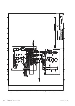
Страница 90: ...art Specification Sheet 051190 0 Page 3 10 Created 2017 03 22 15 47 0 001 MJN MJN 400V 3N 50Hz 16 30kW WIRING DIAGRAM GM HP 16 30 ELSCHEMA GM HP 16 30 051190 0 GreenMaster HP Chapter 11 Technical data 90 ...

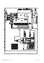
Страница 91: ...art Specification Sheet 051190 0 Page 4 10 Created 2017 03 22 15 47 0 001 MJN MJN 400V 3N 50Hz 16 30kW WIRING DIAGRAM GM HP 16 30 ELSCHEMA GM HP 16 30 051190 0 91 Chapter 11 Technical data GreenMaster HP ...

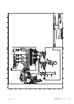
Страница 92: ...art Specification Sheet 051190 0 Page 5 10 Created 2017 03 22 15 47 0 001 MJN MJN 400V 3N 50Hz 16 30kW WIRING DIAGRAM GM HP 16 30 ELSCHEMA GM HP 16 30 051190 0 GreenMaster HP Chapter 11 Technical data 92 ...

Страница 93: ...art Specification Sheet 051190 0 Page 6 10 Created 2017 03 22 15 47 0 001 MJN MJN 400V 3N 50Hz 16 30kW WIRING DIAGRAM GM HP 16 30 ELSCHEMA GM HP 16 30 051190 0 93 Chapter 11 Technical data GreenMaster HP ...

Страница 94: ...art Specification Sheet 051190 0 Page 7 10 Created 2017 03 22 15 47 0 001 MJN MJN 400V 3N 50Hz 16 30kW WIRING DIAGRAM GM HP 16 30 ELSCHEMA GM HP 16 30 051190 0 GreenMaster HP Chapter 11 Technical data 94 ...

Страница 95: ...art Specification Sheet 051190 0 Page 8 10 Created 2017 03 22 15 47 0 001 MJN MJN 400V 3N 50Hz 16 30kW WIRING DIAGRAM GM HP 16 30 ELSCHEMA GM HP 16 30 051190 0 95 Chapter 11 Technical data GreenMaster HP ...

Страница 96: ...art Specification Sheet 051190 0 Page 9 10 Created 2017 03 22 15 47 0 001 MJN MJN 400V 3N 50Hz 16 30kW WIRING DIAGRAM GM HP 16 30 ELSCHEMA GM HP 16 30 051190 0 GreenMaster HP Chapter 11 Technical data 96 ...

Страница 97: ...rt Specification Sheet 051190 0 Page 10 10 Created 2017 03 22 15 47 0 001 MJN MJN 400V 3N 50Hz 16 30kW WIRING DIAGRAM GM HP 16 30 ELSCHEMA GM HP 16 30 051190 0 97 Chapter 11 Technical data GreenMaster HP ...

Страница 98: ... Temperature sensor hot water top 25 F Filling and venting Filling and venting the climate system 35 Filling and venting the climate system 35 H Heating medium side 21 Connecting the climate system 22 Helping the circulation pump to start 42 Hot water heater 22 Connecting the hot water heater 22 I Important information 4 Recovery 5 Inspection of the installation 6 L Level monitor 21 Load monitor 2...

Страница 99: ...tep controlled additional heat 27 System diagram 19 T Technical data 51 Temperature sensor external flow line 25 Temperature sensor hot water charging 25 Temperature sensor hot water top 25 Temperature sensor data 42 Transport and storage 8 U USB service outlet 39 44 99 Chapter 12 Item register GreenMaster HP ...

Страница 100: ......

Страница 101: ......

Страница 102: ......

Страница 103: ......

Страница 104: ...me Gemensamt WS version a613 WS release date 2019 01 02 09 15 Publish date 2019 01 28 16 20 NIBE AirSite AB Elementvägen 1 437 36 LINDOME Phone 46 31 311 32 00 info nibeairsite se www nibeairsite com 431719 ...

Отзывы: