


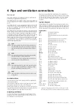


Connection of fire alarm (BR1)
Connect fire alarm (BR1) to accessory board (AA5) ter-
minal block X2:19-20.
21 22
20
19
18
X2
BR1
AA25
External
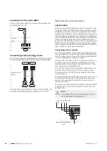
Connecting external energy meter
One or two energy meters (BE6, BE7) are connected to
terminal block X22 and/or X23 on input board (AA3).
F1345
Externt
1
2
3
1
2
3
+5V
+5V
External
GreenMaster-HP
AA3-X22
BE6
AA3-X23
BE7
Activate the energy meter(s) in menu 5.2.4 and then set
the desired value (energy per pulse) in menu 5.3.21.
Optional connections
Load monitor
When many electrical appliances are connected in the
property at the same time as the electric additional heat
is operating, there is a risk of the property's main fuse
tripping. GreenMaster-HP has integrated load monitors
that control the power steps for the electric additional
heat by redistributing the power between the different
phases or disengaging the electric additional heat in
event of an overload in a phase. If the overload remains
despite the electric additional heat being disengaged,
the compressor winds down. Reconnection occurs when
other current consumption is reduced.
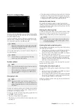
Connecting current sensors
A current sensor (BE1 - BE3) must be installed on each
incoming phase conductor into the electrical distribution
unit, to measure the current. The electrical distribution
unit is an appropriate installation point.
Connect the current sensors to a multi-core cable in an
enclosure next to the electrical distribution unit. Use
unscreened multi-core cable of at least 0.5 mm², from
the enclosure to GreenMaster-HP.
Connect the cable to terminal block AA101-X10:15 to
AA101-X10:16 and AA101-X10:17 as well as to the
common AA101-X10:18 terminal block for the three
current sensors.
The value for the size of the fuse is set in menu 5.1.12 to
correspond with the size of the property’s main fuse.
Here it is also possible to adjust the current sensor’s
transformer ratio.
Enclosed current sensors have a transformer ratio of 300
and, if these are used, the incoming current must not
exceed 50 A.
NOTE
The voltage from the current sensor to the in-
put board must not exceed 3.2 V.
L
PEN
1
L
2
L
3
Electrical distribution
unit
Incoming electricity
GreenMaster-HP
Chapter 5 |
Electrical connections
26


